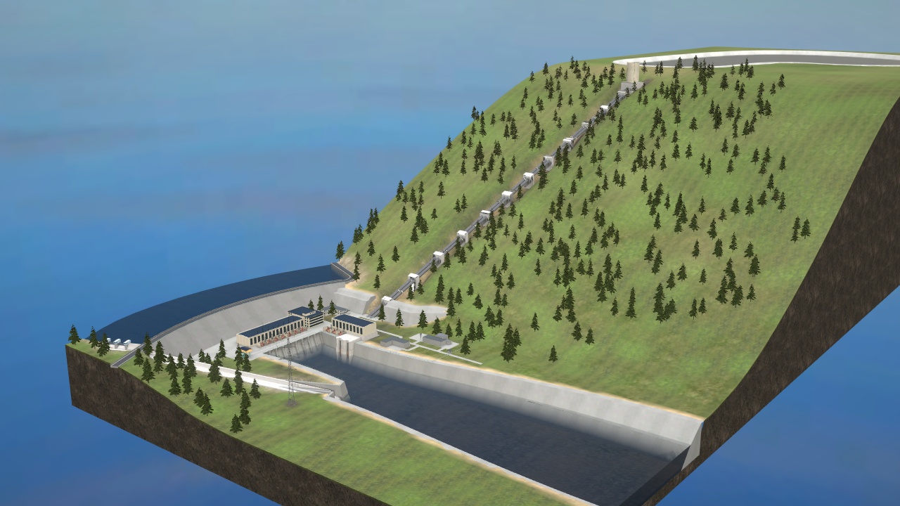
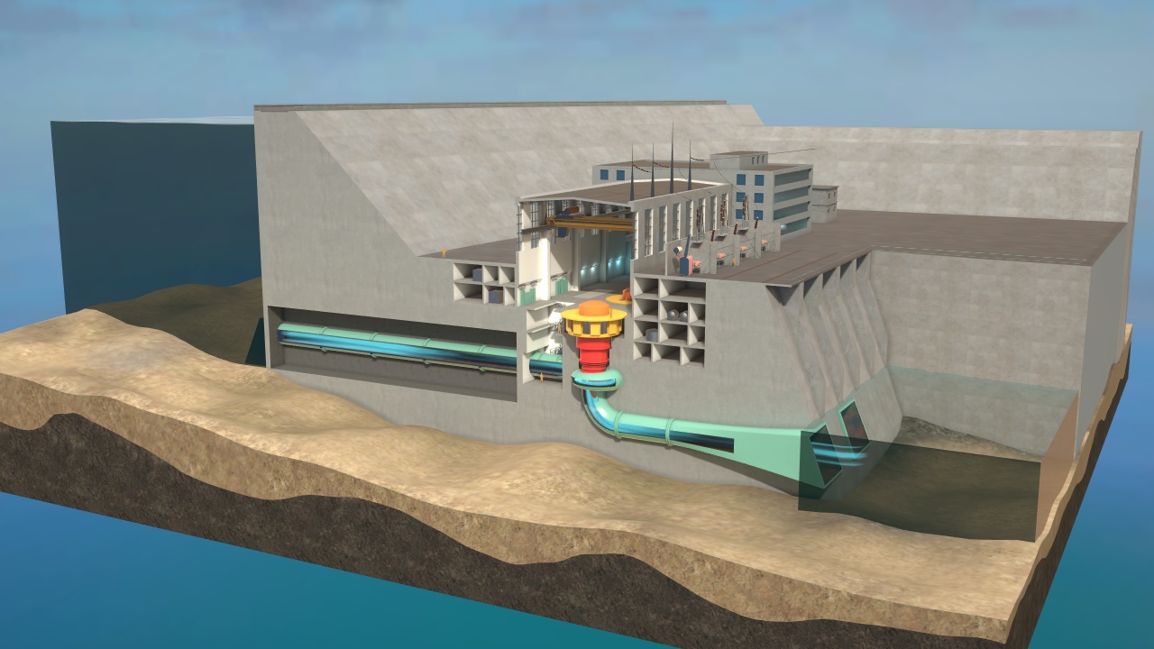
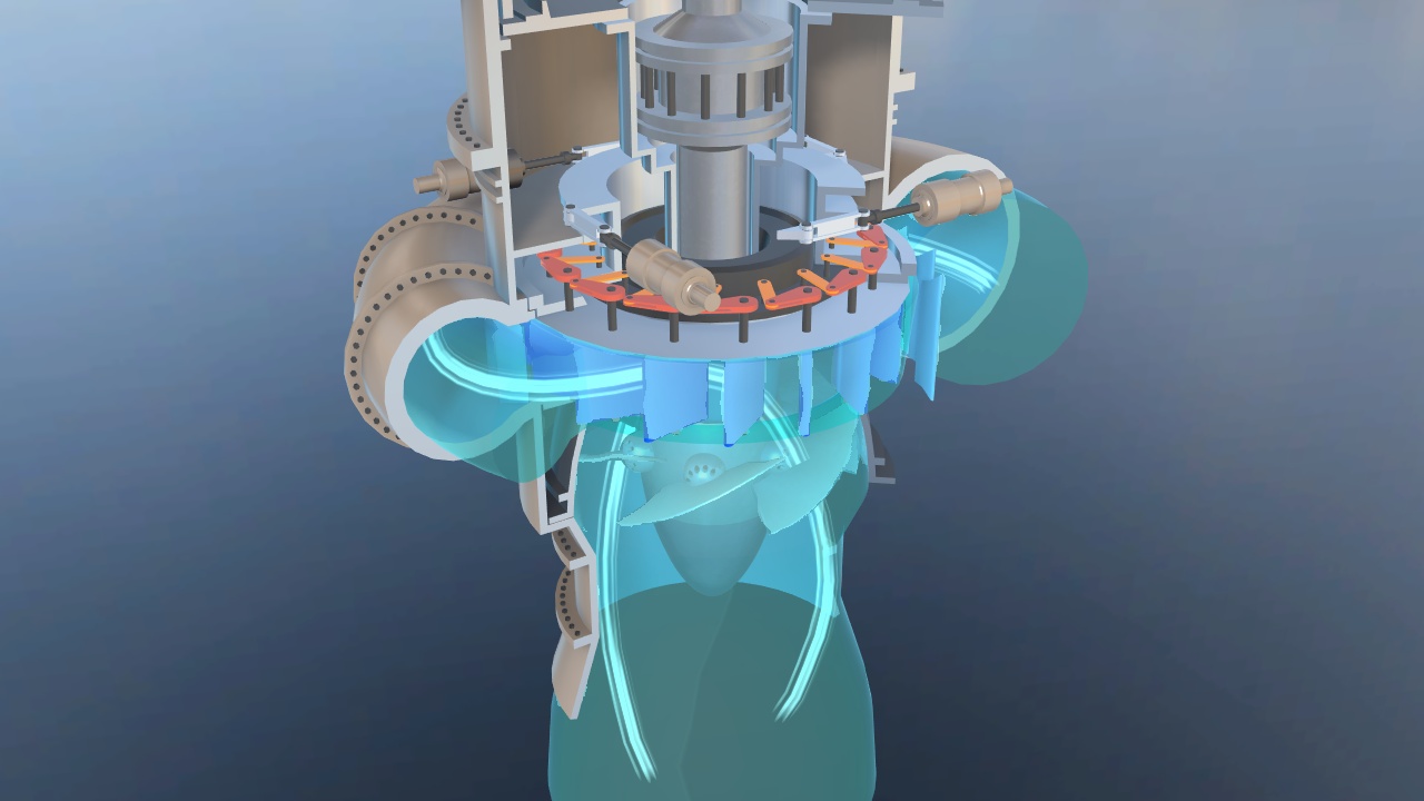
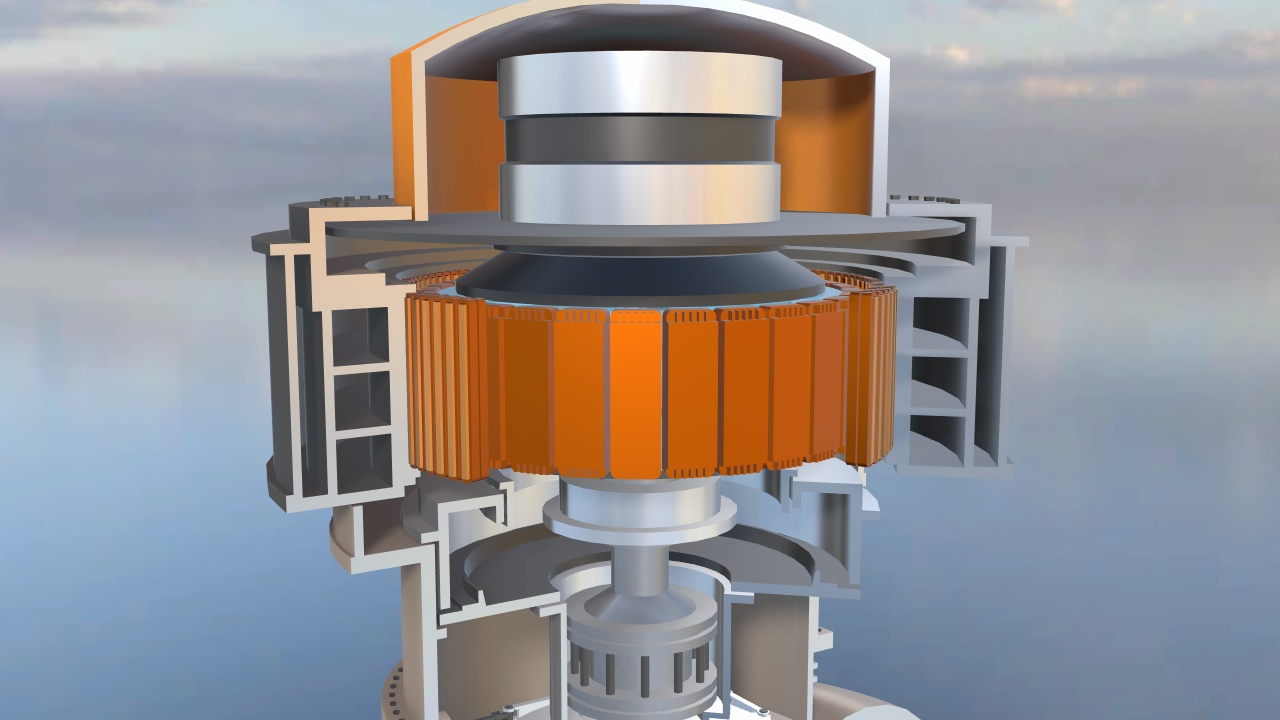
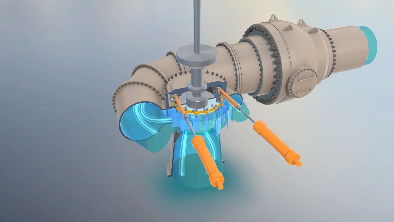
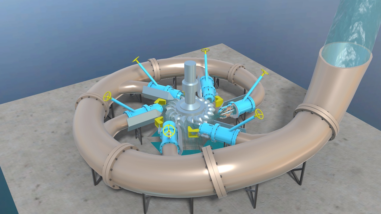
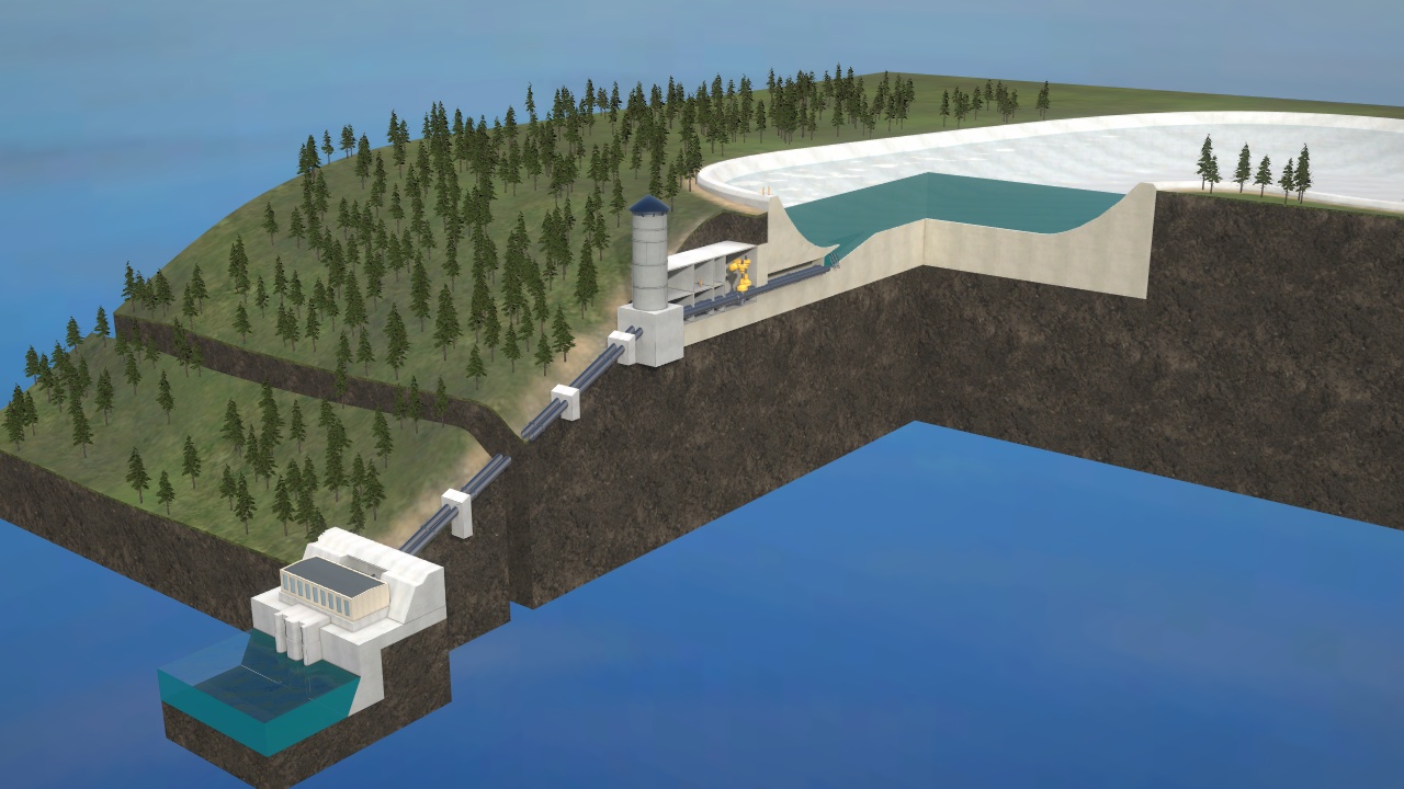
In times of electricity overproduction, this plant consumes electricity and pumps water from the lower reservoir up to the upper one. When the load peaks, when there is not enough energy in the grid, the accumulated water is released to drive turbines and power generators and returns the accumulated energy back to the grid. To produce 1 kW of electricity, a pumped storage plant consumes roughly 1,3 kW during the off-peak time. A significant advantage of pumped-storage power plants is their capacity to quickly change their mode of operation from pumping to power generation within just a few minutes and, in this way, to respond to the actual load situation in the grid dynamically.