What scenes and objects can you find in this model?
NPP unit
Fuel loading machine
The fuel loading machine is a piece of equipment which handles nuclear fuel and is designed for loading and unloading operations with nuclear fuel.
Recirculation circuit
Water must constantly flow through the reactor core. This is ensured by a recirculation circuit. Water is taken from the reactor and pumped through a set of jet pumps to the bottom of the reactor vessel, from where it flows through fuel channels.
Drywell
The reactor’s containment made from reinforced concrete is usually smaller than for a PWR nuclear power plant, because a BWR works with lower temperatures and lower pressures. Due to the presence of steam inside a reactor, drywell is connected to a suppression pool, where in case of accident the steam can be diverted, cooled and condensed.
Power output
There are three different ways to express the power output of a nuclear power plant: 1) Thermal power expressed in MWt is a measure of how much heat is generated by the reactor. 2) Gross electric power output MWe is a measure of how much electricity is generated by the generator. 3) Net electrical power output MWe is a measure of how much electricity is supplied to the grid. Part of the generated electricity is consumed by the power plant itself for production purposes. Since the power output differs between winter and summer, due to seasonal variation in the cooling efficiency, an average power output or the lowest summer output is used.
Suppresion pool
A large pool of water located below the reactor’s pressure vessel. BWRs are equipped with a set of safety valves that vent the excess steam pressure and collect it after condensation a in suppression pool (also called a ‘wetwell’, or ‘wet torus’ in those reactor designs where the suppression pool has a toroidal shape).
Feedwater
After condensed in a condenser, feedwater runs back to the reactor. Because it is in direct contact with nuclear fuel, it has to be very pure to prevent corrosion. The content of radioactive elements in the feedwater is regularly controlled. Higher radioactivity of feedwater could signal damage of the nuclear fuel.
Condenser
The steam from the turbine’s output is condensed inside the condenser. The condenser is a kind of heat-exchanger. The steam gives its heat to cooling water from a secondary cooling circuit. This cooling water can run through cooling towers or can be taken from a river or sea, if such a kind of large water area is available. Cooled water from the primary circuit is then pumped as feedwater back to the reactor.
Steam
The steam from the reactor is led to the turbine.
Cooling
In order to condensate water in the condenser, the heat has to be removed from the steam. This is done by cooling water usually taken from a river, lake or sea. This is why the power plant has to be located on the shore of such a large body of water. Having been used as cooling-water, the water is warmed up. The warmer the water, the less oxygen it contains, which is harmful for fish and other fauna in the river. If the temperature is too high, the cooling water must be additionally cooled down in the cooling towers before its release into the river.
Spent fuel pool
Spent fuel withdrawn from the nuclear reactor is stored under water. The water acts as a radioprotective shielding and as a coolant.
Generator
Stator
In current power systems, a three-phase power line is used, so all power electric generators usually have at least three pairs of stator coils, one for each phase.
Electric generator
An electric generator transfers the rotational movement of the turbine rotor to electric energy using magnetic induction. Electric generators consist of a rotor and a stator. The rotor usually generates a rotating magnetic field, and coils are located in the stator, where electric voltage is induced.
Power output
Power electric generators usually have at least three pairs of stator coils, one for each phase. The resulting electrical current is then led via three encapsulated conductors to a transformer.
Rotor
The electric generator works on the principle of electromagnetic induction - the rotating magnetic field formed by the rotor coils generates an alternating electric voltage in the fixed stator coils.
Fuel assembly
Channel
A square-shaped tube fabricated from Zircaloy 4 encapsulating a fuel bundle. The fuel channels direct the core coolant flow through each fuel bundle and also serve to guide the control rod assemblies - cruciform blades moving in the gaps between every group of four fuel channels.
Part lenght rod
A fuel rod shorter than other fuel rods situated in the lower part of reactor core. Together with the use of different enrichments in different parts of the core, it allows the optimization of thermal and hydraulic performance. The multiple lengths improve the ratio of fuel to moderator to compensate for steam generation.
Fuel rod detail
A fuel rod is a long and narrow hollow Zircaloy tube hermetically sealed on both ends by welding Zircaloy end plugs. Its length varies from 1.8 to 4.5 m and the diameter is about 12 mm. Inside the tube fuel pellets are stacked, fixed by plenum spring on both ends. The narrow gap between the pellet and the casing is usually filled with helium for better heat removal. This gap also provides space for possible pellet expansion caused by heat and gases produced during fission. A Fuel rod also holds radioactive fission products released by the fuel pellets. A BWR uses rods with different uranium enrichments. Some of the rods can contain pellets where uranium oxide is mixed with neutron burnable poison gadolinium - a BWR cannot use boron in water for neutron absorption, so the neutron poison is used to remove excess neutrons from fission reaction to control its course.
Spacer
A zircaloy grid that holds fuel rods at proper locations.
Fuel pellet
A cylindrical form of nuclear fuel made of sintered uranium oxide UO₂. Uranium is enriched with uranium ²³⁵U isotope to various degrees from natural uranium to approx. 2,2%. Because a BWR cannot use boron in cooling water to absorb neutrons, burnable neutron poison like gadolinium is intimately mixed with some of the UO₂ fuel. Fuel pellets are stacked in a zircaloy tube forming a fuel rod.
Fuel assembly
A BWR fuel bundle typically contains 100 rods, which are spaced in a 10x10 square array supported by lower and upper tie plates. Three types of rods are used in a fuel bundle: tie rods, water rods, and standard fuel rods. Tie rods support the weight of the assembly during fuel handling operations when the assembly hangs by the handle. Water rods are hollow tubes through which flows water serving as a moderator. Fuel rods contain uranium fuel pellets and fission reaction is held inside them. Rods are encapsulated in a square-shaped tube called a fuel channel - a fuel bundle and channel together forms a fuel assembly. Between the fuel assemblies, the control rods in the shape of cruciform blades move. During fission reaction the water boils and creates steam, which has a lower moderating effect than liquid water. The upper part of the reactor core contains more steam than the lower part and the rate of neutron moderation varies from place to place depending on water to steam ratio. In order to obtain the best performance and avoid local power peaking, BWR fuel rods have several axial segments with different enrichments and a BWR fuel assembly has several different rods with different enrichments.
Water rod
Two rods in the fuel assembly are water rods, hollow tubes of Zircaloy 2 cladding without uranium fuel. Small holes are located at the lower and upper ends, allowing water to be driven through the rod. The water serves as a moderator (slows down neutrons) and change in its flow inside fuel bundle helps to control the fission reaction course.
Fuel rod
A fuel rod is a long and narrow hollow Zircaloy tube hermetically sealed on both ends by welding Zircaloy end plugs. Its length varies from 1.8 to 4.5 m and the diameter is about 12 mm. Inside the tube fuel pellets are stacked, fixed by plenum spring on both ends. The narrow gap between the pellet and the casing is usually filled with helium for better heat removal. This gap also provides space for possible pellet expansion caused by heat and gases produced during fission. A Fuel rod also holds radioactive fission products released by the fuel pellets. A BWR uses rods with different uranium enrichments. Some of the rods can contain pellets where uranium oxide is mixed with neutron burnable poison gadolinium - a BWR cannot use boron in water for neutron absorption, so the neutron poison is used to remove excess neutrons from fission reaction to control its course.
Reactor core
Steam separator
Before entering the turbine the steam has to be free from all water droplets that could harm the turbine. The steam separator assembly consists of a domed base on top of which is welded an array of standpipes with a three-stage steam separator located at the top of each standpipe. These fixed axial flow-type steam separators have no moving parts and are made of stainless steel. In each separator, the steam–water mixture rises through the standpipe impinging on the vanes, giving the mixture a spin to establish a vortex wherein the centrifugal forces separate the water from the steam in each of the three stages. The steam then leaves the separator at the top and enters the dryer. The separated water exits the lower end of each stage of the separator and flows back to the reactor.
Vessel
The reactor vessel is a pressure vessel with a single full-diameter removable head. The base material of the vessel is low alloy steel, which is clad on the interior except for the nozzles which have a stainless steel weld overlay to provide the necessary resistance to corrosion. In the lower part of the vessel is situated a reactor core with control rods inserted from the bottom of the vessel, in the upper part the steam is formed and dried before it is allowed to flow to the turbine. Since the vessel head is exposed to a saturated steam environment throughout its operating lifetime, stainless steel cladding is not used in its interior surfaces.
Steam dryer
The steam dryer is mounted in the reactor vessel above the steam separator. Steam from the separators flows upward and outward through the drying vanes. It removes all remaining water droplets from the steam before letting it into the turbine.
Recirculation inlet
Feeds water intake into jet pumps. The function of the reactor water recirculation system is to circulate the required coolant through the reactor core. Recirculation pumps are located outside the reactor vessel.
Feedwater inlet
High purity light water is used as a coolant.
Reactor core
A set of nuclear fuel assemblies located in the lower part of the vessel. The fission reaction is held in the uranium fuel and produced heat boils the water flowing through the reactor core. The resulting mixture of water and steam is then separated in the upper parts of the vessel, steam is dried and passed to the turbine. The reactor core consist of 370 - 800 assemblies according to design. Light water serves as a coolant and as a moderator (to slow down neutrons). Its usual operating pressure is around 7 MPa and temperature 285°C. Control rods are inserted from the bottom between fuel assemblies to control the course of fission reaction.
Steam outlet
Dried steam exits the reactor vessel and flows into the turbine.
Recirculation outlet
The function of the reactor water recirculation system is to circulate the required coolant through the reactor core. Recirculation pumps are located outside the reactor vessel.
Vessel support skirt
The reactor stands on a cylindrical concrete pedestal to which it is mounted via the vessel support skirt. The middle part of vessel’s bottom is used for the control rod entrance.
Jet pump
The main function of jet pumps is to force a flow through the nuclear core. It increases the power of the reactor compared to that obtained by natural circulation. 16 - 24 jet pumps are located in the cylindrical annular zone of the reactor and contain no moving parts. Cooling water is supplied into the jet pumps inlet by a recirculation pump located outside the reactor vessel. The water in the jet pump nozzle is accelerated to a high velocity because of the constriction at the nozzle outlet. This fast flow creates a reduced pressure that sucks water from between the core shroud and the vessel’s inner wall. Both streams mix beyond the nozzle aperture resulting in a flow to the base of the core where it is directed to each of the fuel channels.
Control rods
The movable boron-carbide (B₄C) control rods (also called regulating rods) are sufficient to provide reactivity control from a cold shutdown condition to a full load condition. The absorber concentration is decreased by pulling the rods out of the reactor core, causing the reactor power to increase. Inserting more control rods causes the reaction to be inhibited and the power output decreases. Control rods are inserted from the bottom of the reactor vessel, because the reactors upper part is filled with steam with lower moderating power than liquid water. The control rods have a cruciform cross section and move in the gaps between every group of four fuel assemblies. In addition to the use of control rods, it is possible to control the reactor output via the rate of coolant circulation.
Steam turbine
High pressure turbine
Steam enters the turbine with certain internal heat energy, which gradually changes in the individual sections of the turbine by expansion to the kinetic energy of the rotating turbine shaft.
Low pressure turbine
The impeller diameters of the last low-pressure sections are limited by the maximum centrifugal force acting on the blades and thus their length. If there is more steam in the low-pressure area of the turbine, it is necessary to divide it into two, sometimes three, low-pressure parts. For multi-section steam turbines, the impeller diameter of each subsequent section is larger, because the gradual expansion of the steam also increases its volume.
Steam turbine
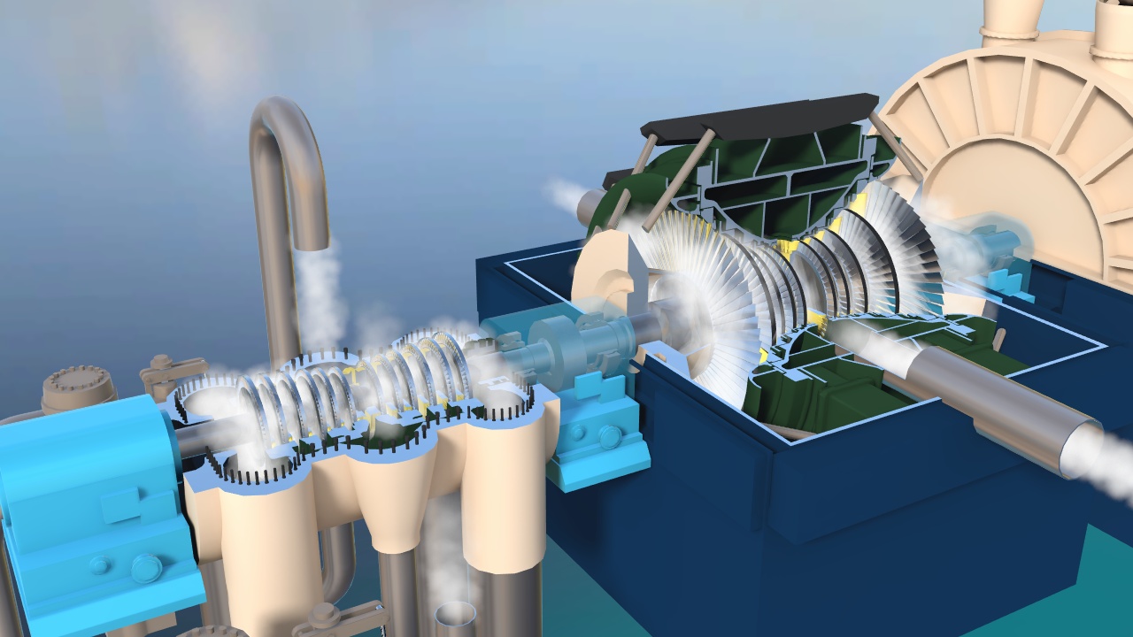
The steam turbine is used to drive an electric generator. A steam turbine is a rotary heat engine that converts the kinetic and thermal energy of flowing steam into mechanical rotary motion transmitted by a mechanical shaft. The turbine consists of one or several sections. Propeller wheels, a part of the machine stator, are called distribution wheels. The others, which are connected to the rotating shaft of the machine, are called impellers and, together with the shaft, form the machine rotor. Large steam turbines are usually divided into several sections– high-pressure and low-pressure, or even medium-pressure. Steam pressure and temperature in a BWR power plant are low compared to a modern coal-fired power plant and the steam turbine is generally very large. Because the steam is exposed to the core, there is some radioactive contamination of the turbines but this is short-lived and turbines can normally be accessed soon after shutdown.