What scenes and objects can you find in this model?
NPP unit
Concrete shielding
Also called containment. A reinforced concrete structure which protects the reactor and other components of the primary circuit and acts as a barrier against ionizing radiation.
More info on www.energyencyclopedia.com/safety-systems
Power output
There are three different ways to express the power output of a nuclear power plant:
1) Thermal power expressed in MWt is a measure of how much heat is generated by the reactor.
2) Gross electric power output MWe is a measure of how much electricity is generated by the generator.
3) Net electrical power output MWe is a measure of how much electricity is supplied to the grid.
Part of the generated electricity is consumed by the power plant itself for production purposes. Since the power output differs between winter and summer, due to seasonal variation in the cooling efficiency, an average power output or the lowest summer output is used.
More info on www.energyencyclopedia.com/the-nuclear-power-plant-how-it-works
Condenser
The steam from the turbine’s output is condensed inside the condenser. The condenser is a kind of heat-exchanger. The condensed steam is then fed through a system of regeneration heat-exchangers back to the steam generator (the secondary circuit is also closed). Heated cooling water from the condenser is cooled in the cooling tower.
More info on www.energyencyclopedia.com/the-nuclear-power-plant-how-it-works
Pressurizer system
Pressure in the primary circuit is maintained by a pressurizer. The pressurizer is partially filled with water which is heated to the saturation temperature (boiling point) by submerged electrical heaters for the desired pressure.
More info on www.energyencyclopedia.com/the-nuclear-power-plant-how-it-works
Main circulation pump
Circulates the primary circuit coolant – the so-called transport of generated heat from the reactor into the steam generators.
More info on www.energyencyclopedia.com/the-nuclear-power-plant-how-it-works
Generator
Stator
In current power systems, a three-phase power line is used, so all power electric generators usually have at least three pairs of stator coils, one for each section.
More info on www.energyencyclopedia.com/the-nuclear-power-plant-how-it-works
Did you know?
As of December 31, 2020, all operational pressurized water reactors (PWR) worldwide together achieved a net electrical power output of 287.1 gigawatts. PWR's are the most common type of nuclear reactors used in nuclear power plants, with 302 in operation at that time. By comparison, boiling water reactors were the second most used reactor type, with a net electrical power of 64.1 gigawatts.
Electric generator
An electric generator transfers the rotational movement of the turbine rotor to electric energy using magnetic induction. Electric generators consist of a rotor and a stator. The rotor usually generates a rotating magnetic field, and coils are located in the stator, where electric voltage is induced.
More info on www.energyencyclopedia.com/the-nuclear-power-plant-how-it-works
Power output
Power electric generators usually have at least three pairs of stator coils, one for each phase. The resulting electrical current is then led via three encapsulated conductors to a transformer.
Rotor
The electric generator works on the principle of electromagnetic induction - the rotating magnetic field formed by the rotor coils generates an alternating electric voltage in the fixed stator coils.
More info on www.energyencyclopedia.com/the-nuclear-power-plant-how-it-works
Fuel assembly
Rod cluster control
Control rods holder that allows the control rods to be moved inside the fuel assembly all at once.
Cladding
Fuel pellets are wrapped into a zircaloy tube.
More info on www.energyencyclopedia.com/pressurized-water-reactor-pwr
Fuel rod detail
A hermetically sealed tube made of zirconium and niobium alloy, and filled with fuel pellets is called a fuel rod. It is usually 4–5 meters long. Each rod contains 350–400 pellets. A single rod contains about 1.5 kg of UO₂. The cladding prevents any direct contact between the cooling water and the fuel, while it has to be transparent to the neutrons. The narrow gap between the pellet and the casing is usually filled with helium for better heat removal. This gap also provides space for possible pellet expansion caused by heat and gases produced during fission.
More info on www.energyencyclopedia.com/fuel-assembly
Support lattice
It is a part of the load-bearing structure of a fuel assembly composed of lattices, a single central channel used for measurements, and 18 guide thimbles for clusters. The lattices support the fuel rods.
More info on www.energyencyclopedia.com/fuel-assembly
Fuel pellet
A Cylindrical form of nuclear fuel made of sintered uranium oxide UO2. The fresh fuel is enriched with uranium ²³⁵U isotope to about 4%–5%. The PWR fuel assembly is composed of uranium cylindrical pellets, 1 cm long and about 8 mm in diameter.
More info on www.energyencyclopedia.com/fuel-assembly
Fuel assembly
PWR fuel assembly usually contains 179–264 rods; the fuel assembly diameter is approximately 20 cm. The rods are structurally supported not to be mutually displaced by the reactor core's extreme thermal and strain stresses. Some assemblies have fewer rods; control and regulating rods are inserted into the resulting gaps. The total fuel, about 121–193 fuel assemblies, is called a fuel load in the reactor core. In total, there are 18 million pellets in the reactor core. The PWR fuel assemblies have a square cross-section; the fuel for the Russian VVER reactors has a hexagonal cross-section.
More info on www.energyencyclopedia.com/fuel-assembly
Regulating rod / Control rod
Control rods (also called regulating rods) made of steel alloyed with boron and containing cadmium or hafnium, are inserted in between the fuel bundles in a nuclear reactor. The absorber concentration is decreased by pulling the rods out of the reactor core, causing the reactor power to increase. Inserting more control rods causes the reaction to be inhibited and the power output decreases. In some types of reactors, the upper part of the fuel bundles is made of absorbing material; the depth of the fuel insertion into the reactor core controls the reactor power.
Fuel rod
A hermetically sealed tube made of zirconium and niobium alloy, and filled with fuel pellets is called a fuel rod. It is usually 4–5 meters long. Each rod contains 350–400 pellets. A single rod contains about 1.5 kg of UO₂. The cladding prevents any direct contact between the cooling water and the fuel, while it has to be transparent to the neutrons. The narrow gap between the pellet and the casing is usually filled with helium for better heat removal. This gap also provides space for possible pellet expansion caused by heat and gases produced during fission.
More info on www.energyencyclopedia.com/fuel-assembly
Steam generator
Feedwater division
Feedwater is evenly split by a system of collectors along the entire steam generator area.
More info on www.energyencyclopedia.com/coolant
Secondary moisture separator
The mechanical two-stage device prevents tiny water droplets from leaving together with the steam. It is located in the top part of the steam generator.
More info on www.energyencyclopedia.com/coolant
Heat-exchange tube bundle
Steam is generated when feedwater comes into contact with the surfaces of hot tube bundles (thousands of small diameter tubes) conducting the primary coolant.
More info on www.energyencyclopedia.com/coolant
Steam outlet
Typically saturated steam from the PWR steam generator has a temperature of approximately 275 °C (527 °F). From the steam generator steam is fed to a steam turbine (secondary circuit).
More info on www.energyencyclopedia.com/coolant
Did you know?
Each steam generator can measure up to 21 m (70 feet) in height and weigh up to 800 tons. Each steam generator can contain from 3,000 to 16,000 heat-exchange tubes.
Primary moisture separator
It prevents tiny water droplets from leaving the steam generator together with steam.
More info on www.energyencyclopedia.com/coolant
Output collector (cold leg)
Coolant, releasing some of its energy in the steam generator, is returned via the output collector, back to the nuclear reactor.
More info on www.energyencyclopedia.com/coolant
Input collector (hot leg)
A cylindrical chamber dividing the heated primary circuit coolant into individual heat-exchange tubes.
More info on www.energyencyclopedia.com/coolant
Reactor core
Reactor pressure vessel
he reactor vessel body is the most significant component of the primary circuit. It contains the fuel assembly, coolant, and fittings to support a coolant flow, and support structures. It is usually cylindrical and is open at the top to allow the fuel to be loaded.
More info on www.energyencyclopedia.com/pressurized-water-reactor-pwr
Inlet nozzle
Input coolant water parameters are 275 °C (527 °F). Despite the high temperature, the water remains liquid due to the high pressure in the primary coolant loop, usually around 15.5 MPa (153 atm). Output cooling water has a temperature of 315 °C (599 °F).
More info on www.energyencyclopedia.com/pressurized-water-reactor-pwr
Control rod drive mechanism
A mechanism on the top of the reactor vessel cover capable of inserting or withdrawing a control rod at a slow, controlled rate, as well as providing a rapid insertion in the event of an abnormal situation.
Reactor core
Heat is generated in a nuclear power plant by the fission of uranium nuclei in the nuclear fuel loaded in the reactor core. Natural or enriched uranium or MOX – a mixture of uranium and plutonium oxides, is usually used to produce nuclear fuel. The PWR reactor core also contains lightweight water as a moderator (used to slow down neutrons) and at the same time as a coolant. Absorber rods (which absorb neutrons) are used to control the course of the fission reaction.
More info on www.energyencyclopedia.com/pressurized-water-reactor-pwr
Outlet nozzle
An output which cools water as it flows upwards towards the reactor whose core is heated to a temperature of 315 °C (599 °F). The Input coolant parameters are 275 °C (527 °F). The water remains liquid despite the high temperature due to the high pressure in the primary coolant loop, usually, around 15.5 MPa (153 atm).
More info on www.energyencyclopedia.com/pressurized-water-reactor-pwr
Neutron reflector
The reactor core is surrounded by a neutron reflector (reactor core baffle) that reflects back neutrons that would otherwise escape. These neutrons are again available for chain reaction.
Control rods
Control rods (also called regulating rods) made of steel alloyed with boron and containing cadmium or hafnium, are inserted in between the fuel bundles in a nuclear reactor. The absorber concentration is decreased by pulling the rods out of the reactor core, causing the reactor power to increase. Inserting more control rods causes the reaction to be inhibited and the power output decreases. In some types of reactors, the upper part of the fuel bundles is made of absorbing material; the depth of the fuel insertion into the reactor core controls the reactor power.
Did you know?
A PWR has about 150-250 fuel assemblies, each assembly containing 200 to 300 fuel rods. It has about 80–100 tons of uranium in its reactor core.
Reactor building
Fuel loading machine
The fuel loading machine is a nuclear fuel handling piece of equipment designed for loading and unloading operations with nuclear fuel.
More info on www.energyencyclopedia.com/pressurized-water-reactor-pwr
Pressurizer system
Pressure in the primary circuit is maintained by a pressurizer. The pressurizer is partially filled with water which is heated to the saturation temperature (boiling point) by submerged electrical heaters for the desired pressure.
More info on www.energyencyclopedia.com/pressurized-water-reactor-pwr
Nuclear polar crane
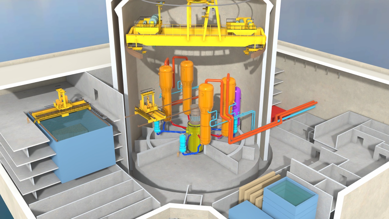
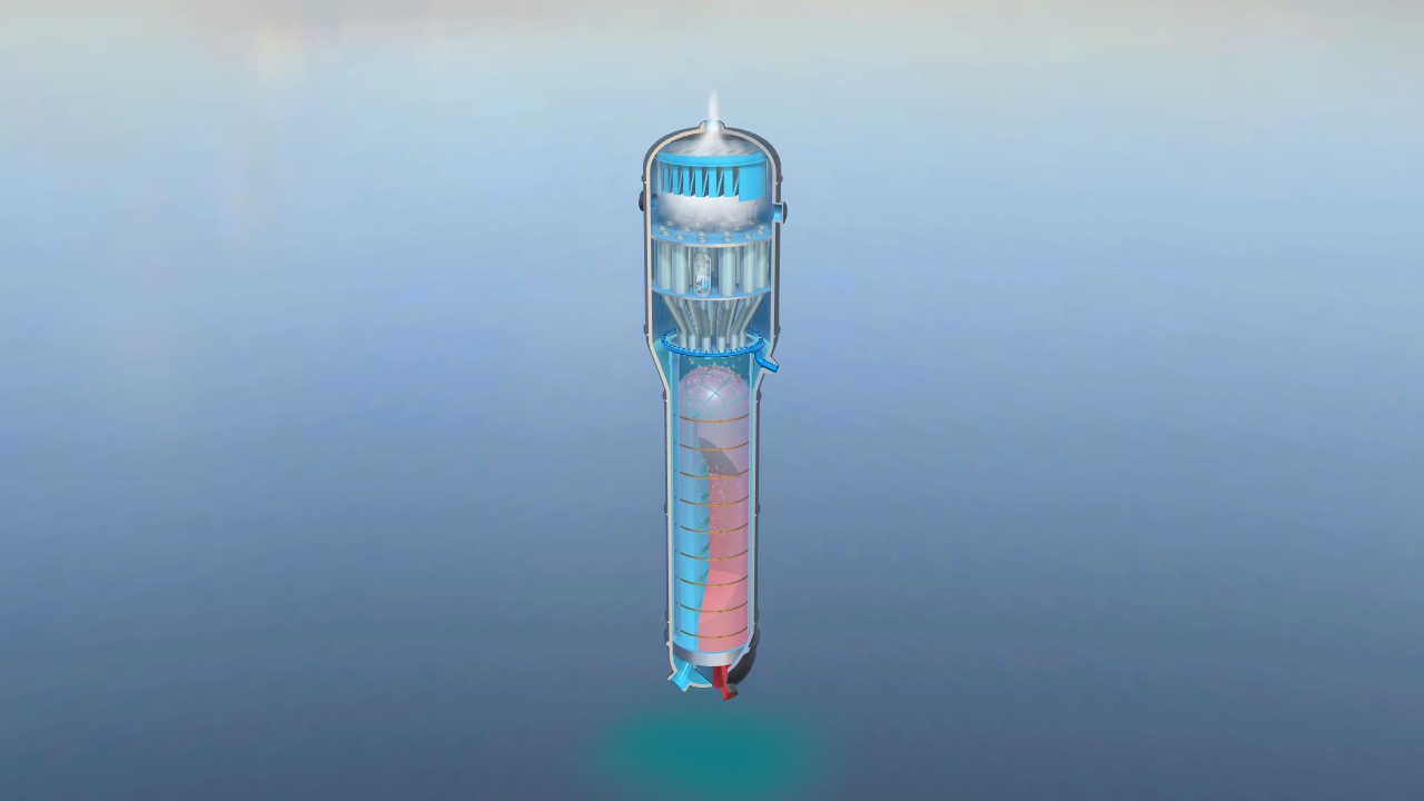
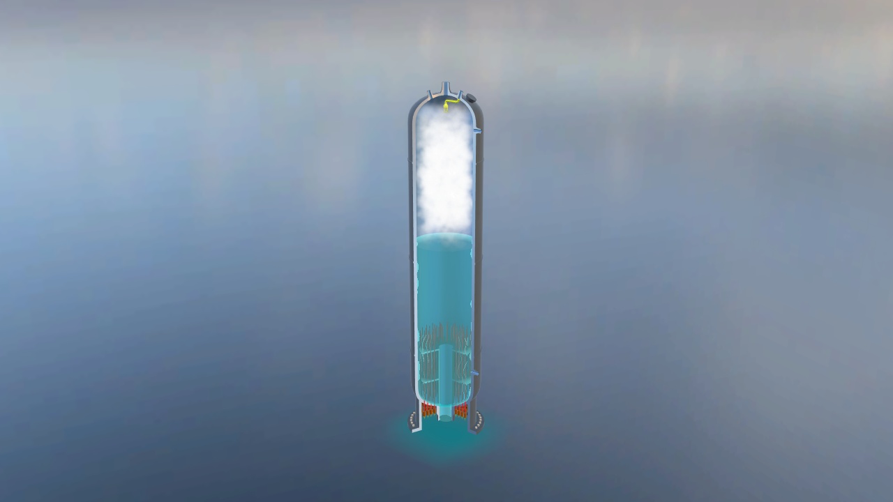
The nuclear polar crane can be used to lift the main equipment of the primary circuit (e.g., steam generator, reactor pressure vessel, pressure vessel top cover, pressing unit, basket, and spent fuel containers) during the nuclear power plant construction, operation, and decommissioning.
More info on www.energyencyclopedia.com/pressurized-water-reactor-pwr
Spent fuel pool
Spent fuel withdrawn from the nuclear reactor is stored under the water. The water acts as radioprotective shielding and as a coolant.
Main circulation pump
Circulates the primary circuit coolant – the so-called transport of generated heat from the reactor into the steam generators.
More info on www.energyencyclopedia.com/pressurized-water-reactor-pwr
Turbine hall
Power output
There are three different ways to express the power output of a nuclear power plant:
1) Thermal power expressed in MWt is a measure of how much heat is generated by the reactor.
2) Gross electric power output MWe is a measure of how much electricity is generated by the generator.
3) Net electrical power output MWe is a measure of how much electricity is supplied to the grid.
Part of the generated electricity is consumed by the power plant itself for production purposes. Since the power output differs between winter and summer, due to seasonal variation in the cooling efficiency, an average power output or the lowest summer output is used.
More info on www.energyencyclopedia.com/the-nuclear-power-plant-how-it-works
1) Thermal power expressed in MWt is a measure of how much heat is generated by the reactor.
2) Gross electric power output MWe is a measure of how much electricity is generated by the generator.
3) Net electrical power output MWe is a measure of how much electricity is supplied to the grid.
Part of the generated electricity is consumed by the power plant itself for production purposes. Since the power output differs between winter and summer, due to seasonal variation in the cooling efficiency, an average power output or the lowest summer output is used.
More info on www.energyencyclopedia.com/the-nuclear-power-plant-how-it-works
Condenser
The steam from the turbine’s output is condensed inside the condenser. The condenser is a kind of heat-exchanger. The condensed steam is then fed through a system of regeneration heat-exchangers back to the steam generator (the secondary circuit is also closed). Heated cooling water from the condenser is cooled in the cooling tower.
More info on www.energyencyclopedia.com/pressurized-water-reactor-pwr
Steam turbine
High pressure turbine
Steam enters the turbine with a certain internal heat energy, which gradually changes in the individual sections of the turbine by expansion to the kinetic energy of the rotating turbine shaft.
More info on www.energyencyclopedia.com/pressurized-water-reactor-pwr
Low pressure turbine
The impeller diameters of the last low-pressure sections are limited by the maximum centrifugal force acting on the blades and thus their length. If there is more steam in the low-pressure area of the turbine, it is necessary to divide it into two, sometimes three low-pressure parts. For multi-section steam turbines, the impeller diameter of each subsequent section is larger, because the gradual expansion of the steam also increases its volume.
More info on www.energyencyclopedia.com/pressurized-water-reactor-pwr
Steam turbine
The steam turbine is used to drive an electric generator. A steam turbine is a rotary heat engine that converts the kinetic and thermal energy of flowing steam into a mechanical rotary motion transmitted by a mechanical shaft. The turbine consists of one or several sections. Propeller wheels, a part of the machine stator, are called distribution wheels. The others, which are connected to the rotating shaft of the machine, are called impellers and, together with the shaft, form the machine rotor. Large steam turbines are usually divided into several sections – high-pressure and low-pressure, or even medium-pressure.
More info on www.energyencyclopedia.com/pressurized-water-reactor-pwr
Cooling tower
Did you know?
The hyperboloid cooling tower was patented by Frederik van Iterson and Gerard Kuypers in 1918.
Cold water
Cooled water is collected in the round pool at the tower base and fed by pumps back to the turbines condenser.
Hot water spray system
The incoming warm water is distributed through spray nozzles installed inside the tower at roughly 10% of its total height. The spray nozzles spray the warm water evenly over the entire fill. Cooling starts as soon as the water exits the nozzles, so it is necessary to maximize the interaction between the hottest water and the coldest air. A nozzle that generates very small droplets will have a greater cooling effect than a nozzle that makes big, fat droplets.
Fill
Cooling is more efficient the more the water surface is in contact with cold air for a long time. Cooling tower fill is used to increase surface contact as well as contact time between air and water, to provide better heat transfer. Fill is located below the spray nozzles. The older cooling towers used splash type fills - a series of wooden slats placed in a staggered formation. Falling water droplets were repeatedly broken apart, enhancing the air to water interface. The splash type fills are still used, but are mostly made from steel or plastic. Most cooling towers use film type fills, where water is made to form thin flowing sheets to expose as much water surface area as possible to the interacting air flow. The film fills come in many different forms, e.g., cross corrugated fill, vertical offset fill or vertical fill. Simply put, it is set of passageways called flutes which water flows through, while cold air rises through them. A variety of flute configurations are available.
Supports
The hyperboloid concrete shell of a cooling tower is stands on a series of supporting concrete struts. Large amounts of cold outside air can be sucked through the gaps between these diagonal columns.
Hot water
Hot water is pumped from the condenser to a cooling tower.
Tower shell
Cooling towers with a natural air draft have the shape of a rotational hyperboloid (a surface that may be generated by rotating a hyperbola around one of its principal axes). This shape requires the least amount of concrete to be needed for such a big structure, gives the cooling tower an ability to withstand the force of cross-winds, and accelerates the air flow through the tower, which increases the tower’s cooling capacity. The natural draft is created by the density difference between moist warm air inside the tower and cold dry air outside the tower. Moist warm air has a lower density than drier air, and so rises up, and the moist air’s buoyancy produces a current of air through the tower. At the wide base, there is enough space for a cooling system which sucks large amounts of cold air from outside. At the middle of the towers’ height the air speed increases and its density decreases. After expansion from a wider opening, the air cools quickly and is violently mixed with outside cold air. The cooling towers are very large structures, with bases as wide as 100 m and up to 200 m tall.
Water distribution
Hot water is distributed to the spray nozzles by piping or by concrete flumes that ensures an even distribution of warm water to all spray nozzles.
Drift eliminators
The air rising from the cooling tower carries small water droplets. To minimize water loss in the exhaust air it has to pass through a system of baffle-like devices called drift eliminators. The direction of air travel is altered by the eliminators foils or blades. This causes water droplets entrained in the airstream to collect on the eliminator foil surfaces. The droplets agglomerate and they rapidly gain sufficient size and mass to overcome the discharge airstream velocity and drain back into the cooling tower.