What scenes and objects can you find in this model?
Superphénix
Storage drum
A cylindrical vessel filled with hot liquid sodium, used for storage of fresh subassemblies before they are inserted into the reactor, and also for used or irradiated subassemblies, allowing decay of their residual power before they can be cleaned and transported to the spent fuel pool. The storage drum is 13 meters high, is 9 meters in diameter and contains about 800 m³ (700 tons) of sodium at a nominal temperature of 200°C. Subassemblies from the reactor are inserted into the storage drum by charge / discharge ramps and stored in a carousel. The drum is covered with a concrete slab fitted with a rotating plug with a manipulator. The plug can rotate the manipulator over the selected subassembly so it can be removed from the drum, or the manipulator can insert fresh fuel subassembly on a selected place of the carousel.
Pumping station
An intake of cooling water from The Rhone River. A continuous flow of water is used to cool the tertiary circuit.
Secondary circuit
The Superphénix primary circuit is located inside the reactor vessel and contains about 3300 tons of sodium which flows through the reactor core. There are four primary loops. Hot sodium (545°C) flows to the part of the reactor vessel called the hot pool and then to the intermediate heat exchanger, where it pass its thermal energy to sodium of the secondary circuit. The cooled primary sodium (392°C) leaves the intermediate heat exchanger into the part of the reactor vessel called the cold pool. From the cold pool it is pumped by the primary pump to the diagrid below the core. The diagrid ensures even distribution of sodium flow to all subassemblies.
Reactor building
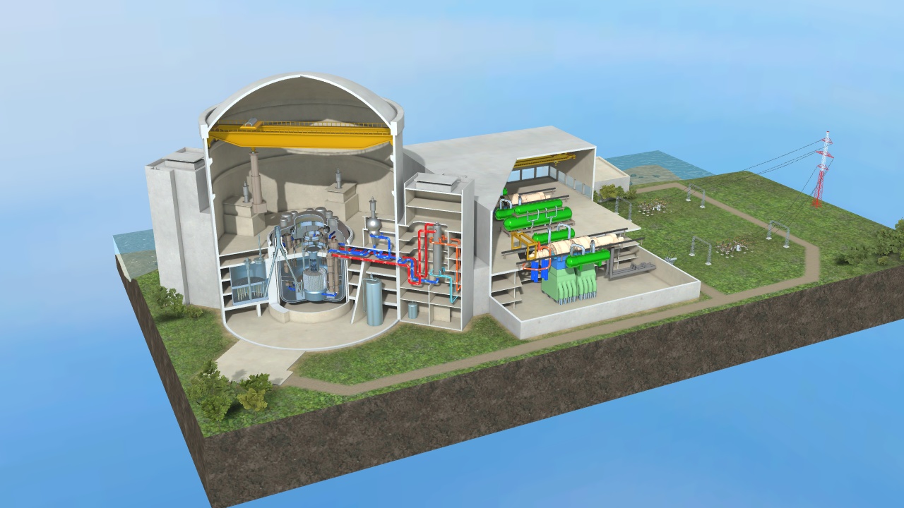
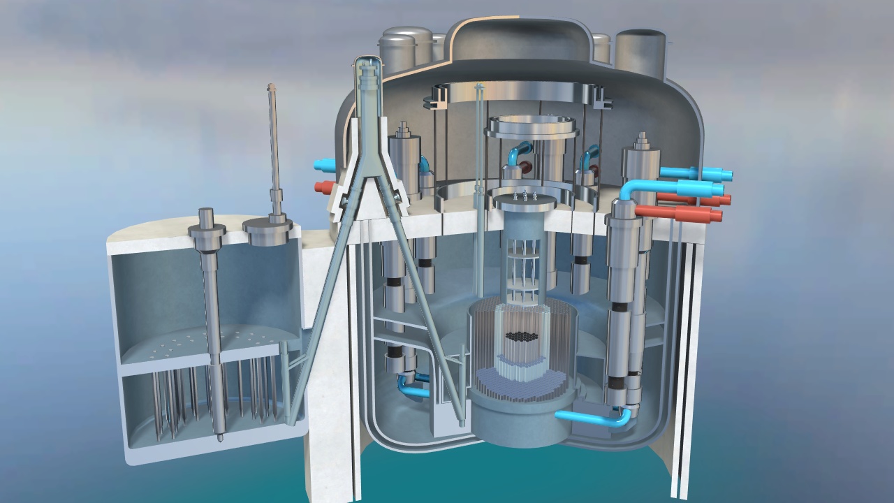
A cylindrical enclosure in reinforced concrete that houses the reactor block and its auxiliary circuits, a part of the secondary loops and fuel handling facilities. It is 84 meters high, is 66 meters in external diameter and its walls are 1 meter thick in the lower part of the building. The atmosphere inside is held at a slightly subatmospheric pressure, so that in case of radionuclide leak , the leak will not be blown into the air, but remain inside the building.
Power output
There are three different ways to express the power output of a nuclear power plant: 1) Thermal power expressed in MWt is a measure of how much heat is generated by the reactor. 2) Gross electric power output MWe is a measure of how much electricity is generated by the generator. 3) Net electrical power output MWe is a measure of how much electricity is supplied to the grid. Part of the generated electricity is consumed by the power plant itself for production purposes. Superphénix had a rated power of 1200 MWe (1240 MWe gross, 3000 MWt). Although it was operated for 11 years, it has generated electricity for only 53 months of normal operation mostly at low power.
Main sodium storage tank
Molten sodium is used as a coolant for the primary and secondary circuits. It is stored at a temperature of about 180°C - sodium's melting point is 97°C. Sodium’s boiling temperature is 883°C. Sodium is highly reactive and its contact with moisture in the air must be prevented.
Secondary circuit
To prevent any reaction between water and the primary sodium, four independent secondary circuits ensure heat transfer from the intermediate heat exchangers onto steam generators by sodium circulation. One loop contains about 325 tons of sodium. The secondary sodium is not radioactive because of neutron shielding around the core. Hot sodium (525°C) exits the intermediate heat exchanger and goes to the steam generator, where it passes heat to water of the tertiary circuit and turns it into steam. Cooled sodium (345°C) leaves the steam generator, enters the secondary pump and is discharged toward the upper part of the intermediate heat exchanger.
Condenser
The steam from the turbine’s output is condensed inside the condenser by water from The Rhone River in an open circuit from the pumping station. The condensed steam is then fed through a system of regeneration heat-exchangers back to the steam generator.
Tertiary circuit
The tertiary circuit contains water. Water is heated in the steam generator to a temperature of about 490°C and turns into superheated steam. The steam propels two turbines, which in turn propels generators to produce electricity. Steam leaving the turbine is cooled and condensed in a condenser and is pumped back into the steam generator.
Nuclear polar crane
The reactor servicing crane, or polar crane, operates on a circular runway located near the spring line of the reactor building. The crane is primarily used for handling heavy reactor equipment such as the primary pump or intermediate heat exchanger. It has a load capacity of 350 tons.
Secondary circuit pump
The secondary circuit also contains sodium, whose continuous flow is ensured by the secondary circuit pump. There are four secondary circuits with four secondary pumps. These are centrifugal devices with a vertical axis, whose expansion tank is immersed in cold sodium (about 200°C). The motor is connected to the pump via a leaktight shaft.
Reactor
Transfer machines
Machines for the manipulation of subassemblies using strong straight-pull grippers. Strength of the gripper is necessary - the subassembly swells during operation and with some sodium deposition on its surface sits tightly in the diagrid. The transfer machines instrumentation enables them in particular to detect excessive forces while seizing a subassembly.
Charge / discharge bay
A location in the reactor vessel where subassemblies can be inserted into a special wheeled sodium-filled pot, in which they can then be hoisted onto the primary ramp in order to be transferred to a storage drum.
Storage drum manipulator
Machine that uses a gripper that can pick up the subassembly from its position on the carousel, move it to another location on the carousel, to the special pot that will transport it through the charge / discharge ramp into the reactor, or remove it from the storage drum in order to be cleaned and moved to a spent fuel pool.
Primary pump motor
Motors driving the primary pumps are located in the dome, above the slab, and are connected to pumps via leaktight shafts.
Pool of molten sodium
The superphénix reactor is a 'pool type’ breeding reactor (or so called integrated type reactor), where the reactor core and primary circuit is submerged in one big basin of molten sodium with an open surface. The upper part of the reactor vessel above sodium level is filled with argon gas. There is about 3300 tons of around 400°C hot sodium.
Rotating plugs
There are two rotating plugs in the slab. The larger one is 12 meters in diameter, the smaller, placed inside the larger one, is 10 meters in diameter. Together they weigh about 850 tons. By rotating the plugs, transfer machines installed in the plugs can be adjusted precisely over the selected subassembly and the plugs can be pulled out by a gripper. The leaktightness of the plugs is ensured by a tin-bismuth eutectic alloy which is solid at the reactor’s normal operation temperature, but liquified by heating resistance to allow the rotating plug to rotate.
Storage drum
A cylindrical vessel filled with hot liquid sodium, used for storage of fresh subassemblies before they are inserted into the reactor, and also for used or irradiated subassemblies, allowing decay of their residual power before they can be cleaned and transported to the spent fuel pool. The storage drum is 13 meters high, is 9 meters in diameter and contains about 800 m³ (700 tons) of sodium at a nominal temperature of 200°C. Subassemblies from the reactor are inserted into the storage drum by charge / discharge ramps and stored in a carousel. The drum is covered with a concrete slab fitted with a rotating plug with a manipulator. The plug can rotate the manipulator over the selected subassembly so it can be removed from the drum, or the manipulator can insert fresh fuel subassembly on a selected place of the carousel.
Rotating transfer lock
The upper part of the charge / discharge ramp where the special on-wheel sodium-filled pot containing subassembly pivots so as to change direction from one ramp to another.
Intermediate heat exchanger
Intermediate heat exchangers are situated in the reactor vessel’s 'hot pool' suspended from a slab and transfer heat from the primary sodium to a secondary circuit also containing molten sodium. They are about 2 meters in diameter and 20 meters tall. They consist of 5380 straight tubes 6,5 meters long through which flows the secondary sodium. The primary sodium enters the intermediate heat exchanger at the top, flows from the top to the bottom on the outside of the tubes, and leaves at the bottom into the 'cold pool'. Thermal power output of one intermediate heat exchanger is 375MW. There are 8 intermediate heat exchangers.
Primary pump
Primary circuit pumps are centrifugal with vertical axis and are immersed in a 'cold' sodium pool. They suck sodium coming out of the intermediate heat exchangers and pump it beneath the reactor core into the diagrid. They are about 3 meters in diameter and 20 meters tall. The primary pump’s nominal speed is 433 revolutions per minute and the flow rate about 4,4 tons of sodium per second. Motors driving the primary pumps are located in the dome, above the slab, and are connected to pumps via leaktight shafts. There are 4 primary pumps in the Superphénix reactor.
Reactor
The superphénix reactor is a fast breeder pool type reactor. A primary circuit with pumps and intermediate heat exchangers are immersed in a pool of liquid sodium which serves as a coolant. Its purpose is to reprocess used fuel from other power plants as well as produce its own fuel. The core of the reactor consists of a mixture of uranium and plutonium (plutonium comes from reprocessed fuel) surrounded by a fertile blanket made from non-fissile uranium U238. The uranium in the blanket is converted by fast neutrons from a fission reaction to fissile Pu239. The blanket is surrounded by neutron shielding.
Dome
A steel covering of the upper part of the reactor located above the slab. It provides protection to the emergency cooling circuit or primary pumps motors. The dome can withstand overpressure of 3Atm.
Storage drum carousel
A rotating part inside the storage drum vessel in which subassemblies can be plugged in concentric rings. By the combined rotation of the carousel and manipulator on a rotating plug, every position in the carousel can be reached. When loading fresh fuel to the reactor, fuel subassembly is first inserted through the manipulator into the carousel. Then it is moved to the charge / discharge ramp and sent to the reactor. Spent fuel (irradiated fuel subassemblies) is transferred to a storage drum after c. 640 equivalent full power days and are left there to allow for the decay of their residual power from 28 to 7.5 kW before being cleaned and stored in the on-site water pool. Fertile subassemblies remains in the reactor for a longer time, but then are also moved to a storage drum.
Vessel
The Reactor’s primary vessel is a steel cylinder 17,3 meters high and 21 meters in diameter. It is filled with about 3300 tons of sodium ensuring core cooling, topped with a cover gas, argon. Argon has a higher than atmospheric pressure which prevents the sucking in of oxygen into the vessel in the case of a leak. Inside the vessel is the submerged reactor core and primary circuit. The vessel is closed by a slab. The interior is divided into internal vessels of ‘cold pool’ and ‘hot pool’. The hot pool consists of the reactor core and hot sodium rising from it and entering intermediate heat exchangers. Cooled sodium exits the intermediate heat exchangers into the cold pool and is pressed by primary pumps on the bottom of the vessel, where the diagrid distributes the sodium flow to individual subassemblies.
Charge / discharge ramp
A ramp which serves as a means to transfer subassemblies between the reactor and the storage drum. The subassembly that is to be moved from the core is picked up by the manipulator and transferred to the charge / discharge bay, where it is inserted into a special on-wheel sodium-filled pot that drives it upwards via the primary ramp, pivots in a rotating transfer lock so as to go along the secondary ramp, and then is transported by a secondary ramp down to the storage drum. The opposite process can be used when transporting fresh fuel subassembly to reactor.
Diagrid
The diagrid is located below the reactor core and ensures the distribution of the sodium core cooling flow between the various subassemblies.
Slab
The reactor vessel is covered by a heavy metallic slab filled with concrete serving as a bioshield. In the center of the slab are two rotating plugs enabling manipulation of the fuel subassemblies. The primary pumps and intermediate heat exchangers are suspended from the slab.
Reactor core
Fissile core
Contains fuel subassemblies in which the fission reaction is held. There are two zones, the inner and the outer, which differ in their plutonium enrichment.
Steel reflector
Enhance core neutron balance by reflecting the neutrons and protect peripheral structures from neutron flux.
Reactor core
The superphénix’s reactor core consists of hexagonal subassemblies of various types arranged on the diagrid. In the middle is a fissile part consisting of an inner and outer zone. This is surrounded by a fertile blanket, which is surrounded by steel reflectors, and finally by neutron shielding. The height of the fertile and fissile part of the reactor core is 1,7 meters and is 4,7 meters in diameter. There are 360 fuel subassemblies in the fissile part, 190 in the inner zone and 170 in the outer zone. They contain a mixture of UO₂ and PuO₂ with plutonium enrichment of 15% in the inner zone and 19% in the outer zone. Between the fuel subassemblies are inserted control rods - absorbent subassemblies - containing boroncarbide that absorbs neutrons. There are 21 control rods of SCP type and 3 of CAS type. The fertile zone (blanket or breeder) contains 230 subassemblies made from depleted uranium. Steel reflectors are arranged around the blanket. There are 12 free spaces in this zone designed to receive any subassembly (e.g. damaged) while awaiting its unloading. The outer edge of the reactor core is completed by a ring of 1076 subassemblies of lateral neutron shielding.
Neutron shielding
Protect the reactor’s internals, such as the intermediate heat exchangers and primary pumps, from neutron flux.
Control rods driving mechanism
Control rods are cylindrical devices sliding in hexagonal sheaths. They are held in their positions above the reactor core by electromagnets.
Subassemblies
Fertile subassembly
Fertile subassembly has shape of hexagonal tube, 5,4 metre high and 17,9cm in maximal diameter. Inside is 91 pins containing depleted, nonfissile uranium oxide in the form of cylindrical pellets stacked in an austenitic steel clad. Pins are surrounded by spacer wire helically wound to prevent direct contact between pins and to optimize heat exchange. Fertile pin is 1,9 metre long and whole fertile subassembly weights 750kg.
SAC control subassembly
SAC (complementary shutdown system) control rods comprise a train of three individual absorber units running in a hexagonal outer steel tube connected together and to a control mechanism by universal joints. This composition gives them high fall reliability including cases of significant core distortion.
SCP control subassembly
Rods of the SCP (main control system) type consist of a mobile part sliding into a hexagonal sheath. Its outer size is similar to fuel subassembly. The moving part inside is a steel cylinder containing 31 pins consisting of boroncarbide canned in a steel tube. Gaps are filled with 8 steel pins of adequate shape and all free space between all pins is filled by sodium. One SCP absorbent rod weights 425kg.
Steel reflector subassembly
Steel reflector subassemblies are of a cylindrical shape but with a hexagonal head. Their purpose is to scatter neutrons back to the reactor core.
Fuel subassembly
Fuel subassembly has shape of hexagonal tube, 5,4m high and 17,9cm in maximal diameter. Inside is 271 pins containing mixed oxide UO₂ - PuO₂ fuel. Pu enrichment is 15% for inner core zone and 19% for outer core zone. Fuel is in the form of cylindrical oxide pellets with a 2 mm central hole stacked in an austenitic steel clad. Pins are surrounded by spacer wire helically wound to prevent direct contact between pins and to optimize heat exchange. Middle part of the pin is 1 metre high fissile part containing fuel, the upper and lower parts contain fertile uranium pellets without central hole. This is the part of upper and lower axial blanket and is 30cm high each. Lower part of subassembly is cylindrical foot that is placed into the diagrid with six holes for sodium supply. Upper part of subassembly is hexagonal steel block with central hole for sodium channeling, serves as upper neutron shielding. One subassembly weights 600kg.
Control subassembly
The purpose of control rods (or absorbent subassemblies) is to absorb neutrons and provide a safe shutdown of the reactor if and when needed. There are two types of absorbent subassemblies - SCP (main control system) and SAC (complementary shutdown system). Rods are held in their position above the reactor core by electromagnets.
Neutron shielding subassembly
Neutron shielding subassemblies are made of steel with boroncarbide. They have to absorb neutrons rather than scatter them.
Steam generator
Water inlet
Water is distributed from four external boxes to 357 heat exchange tubes.
Steam generator
A device that transfers heat from the secondary sodium to water of the tertiary circuit and changes it into steam. There are four steam generators at Superphénix, located in separate buildings adjoining the reactor building, each of a thermal output of 750 MW. One steam generator is a steel cylinder 22,5 meters high and 2,9 meters in diameter and weighs 194 tons. Sodium enters the steam generator’s upper part and flows to the bottom. In the lower part of the steam generator, the water is distributed into 357 tubes helically wound around a central cylindrical support. Each tube is 92 meters long. The tubes are joined together in a manifold outside the steam generator vessel. Outcoming steam is 490°C under 180bar.
Helically wound tubes
357 heat exchange tubes containing water (turning into steam) are helically wound around the central cylindrical support. Each tube is 92 meters long. Sodium flows around them from top to bottom.
Steam outlet
Heat exchange tubes containing steam 490°C hot are joined together outside the steam generator vessel.
Sodium outlet
The cold secondary sodium (345°C) exits the steam generator at the bottom.
Sodium inlet
The secondary sodium is 525 °C and enters the steam generator at its upper part.
Turbine
High pressure turbine
Steam coming from steam generators enters the turbine with internal heat energy, which changes to kinetic energy of the rotating turbine shaft. The pressure of steam exiting at a high-pressure from the turbine is reduced, but the steam still has a lot of energy that is used in two low-pressure turbines.
Low pressure turbine
For multi-stage steam turbines, the impeller diameter of each subsequent stage is larger, because the gradual expansion of the steam also increases its volume. The impeller diameters of the low-pressure stages are however limited by the maximum centrifugal force acting on the blades and thus their length. So the low-pressure stage consists of two turbines.
Steam turbine
The steam turbine is used to drive an electric generator. A steam turbine is a rotary heat engine that converts the kinetic and thermal energy of flowing steam into a mechanical rotary motion transmitted by a mechanical shaft. Propeller wheels, part of the machine stator, are called distribution wheels. The others, which are connected to the rotating shaft of the machine, are called impellers and, together with the shaft, form the machine rotor. The Superphénix has two turbogenerator sets of electrical output of 620MW each. The turbine is an action type and consists of a single flux high-pressure body and two dualflux low-pressure bodies. Steam coming from the steam generator works in a high-pressure turbine, then is sent to two separators-reheaters and then propels two low-pressure turbines. Steam coming out from the low-pressure turbine is cooled and condensed in a condenser.
Eletric generator
Stator
In current power systems, a three-phase power line is used, so all power electric generators usually have at least three pairs of stator coils, one for each phase.
Electric generator
An electric generator transfers the rotational movement of the turbine rotor to electric energy using magnetic induction. Electric generators consist of a rotor and a stator. The rotor generates a rotating magnetic field, and coils are located in the stator, where electric voltage is induced.
Power output
Power electric generators usually have at least three pairs of stator coils, one for each phase. The resulting electrical current is then led via three encapsulated conductors to a transformer.
Rotor
The electric generator works on the principle of electromagnetic induction - the rotating magnetic field formed by the rotor coils generates an alternating electric voltage in the fixed stator coils.