
Types of Wind Turbines
8 min read
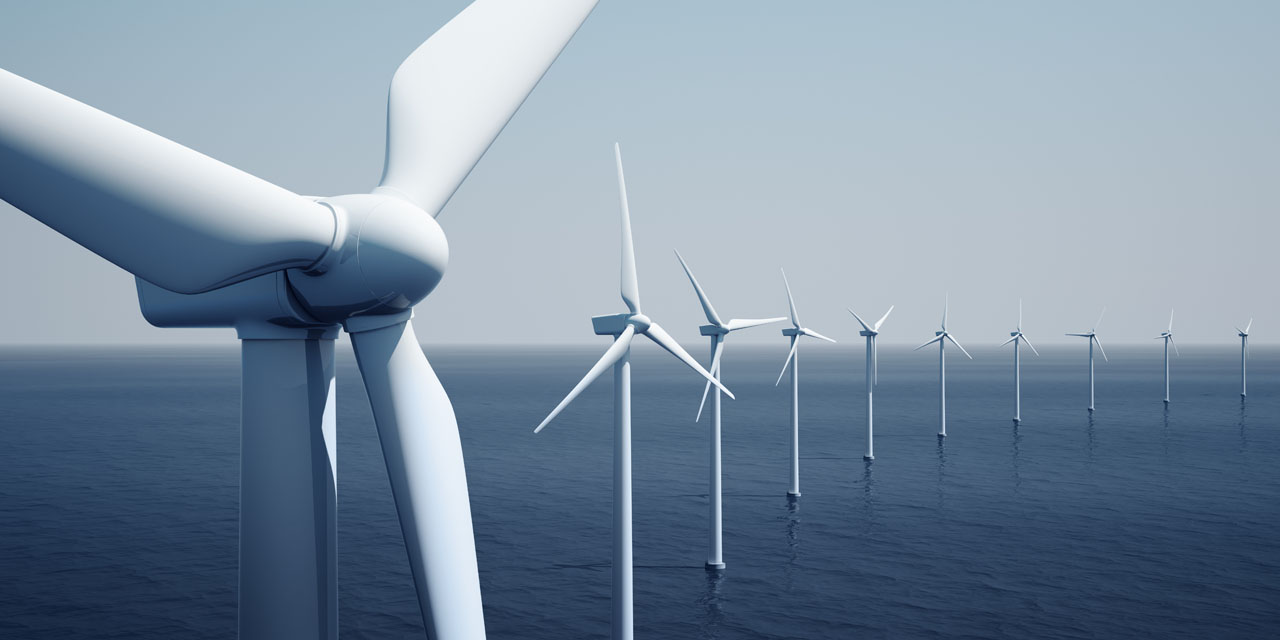
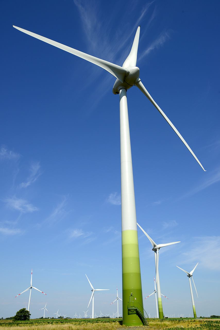
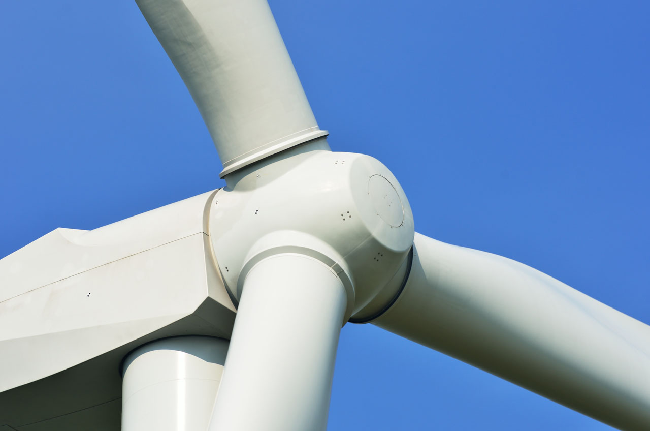
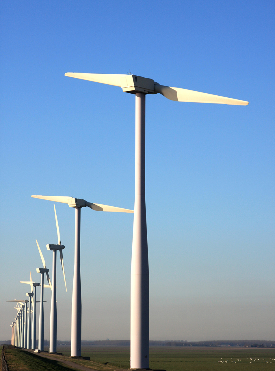
Horizontal Axis Wind Turbine
Video: 3D model of a horizontal axis wind turbine.
Free Downloads › Animations
This is the most common type of wind turbine. The blades are designed to generate a lift force perpendicular to the direction of the airflow. The rotor diameter can be up to 100 meters and the efficiency lies around 45%.
Wind turbines with a horizontal axis constitute the majority of commercially produced installations. Their main parts are: a two or more and often a three-bladed rotor, a shaft, a gearbox and an electric generator. The whole aggregate is fitted into a turning nacelle mounted on top of a steel or reinforced concrete tower. Small turbines use wind vanes to turn the propeller against the wind. Bigger and more powerful turbines are turned by servomotors which are controlled electronically based on the output of wind direction sensors. Most horizontal axis turbines are positioned on the upwind side of the tower to avoid aerodynamic disturbance from the tower but they must have stiffer and stronger blades, further away from the tower. Downwind propellers do not have this problem and it is easier to turn them with the wind but the turbulence from the mast causes fatigue and shortens their life span. Today most horizontal wind turbines are equipped with an upwind rotor.

Online 3D Model
Free Downloads › Online 3D
The tip speed ratio of modern horizontal axis turbines reaches the value of 6. This means that at wind speeds of 50 km/h, the blade tips move at 300 km/h. With blades 40 meters long, the rotor of a given turbine revolves approximately 20 times in a minute. But that is just too slow to drive an electric generator which requires at least 1,000. That is why a gearbox must be used, which increases the number of revolutions at the expense of torque. There are other types of wind turbines that do not need a gearbox since they use a special multipolar electric generator that can be connected directly to the main shaft of the turbine.
The output performance of modern horizontal axis wind turbines lies in the region of individual MW. If higher output is required, wind farms are built with multiple turbines. The usual estimated life span of a wind turbine can be between 20 and 25 years with 120,000 hours of operation.
14 pictures
14 pictures
Produced blades are assorted according to their weight, weight distribution and frequency so that the blades in one rotor are as similar as possible.
The rotor blade length is attacking the value of 60 meters which represents a great challenge for transportation. That is why the Enercon Company is trying out new two part blades at the Estinnes wind farm in Belgium.
12 to 45 mm (exceptionally even 70 mm) thick steel plates are used to build 70 to 100 meter high steel towers.
Vertical Darrieus Wind Turbine
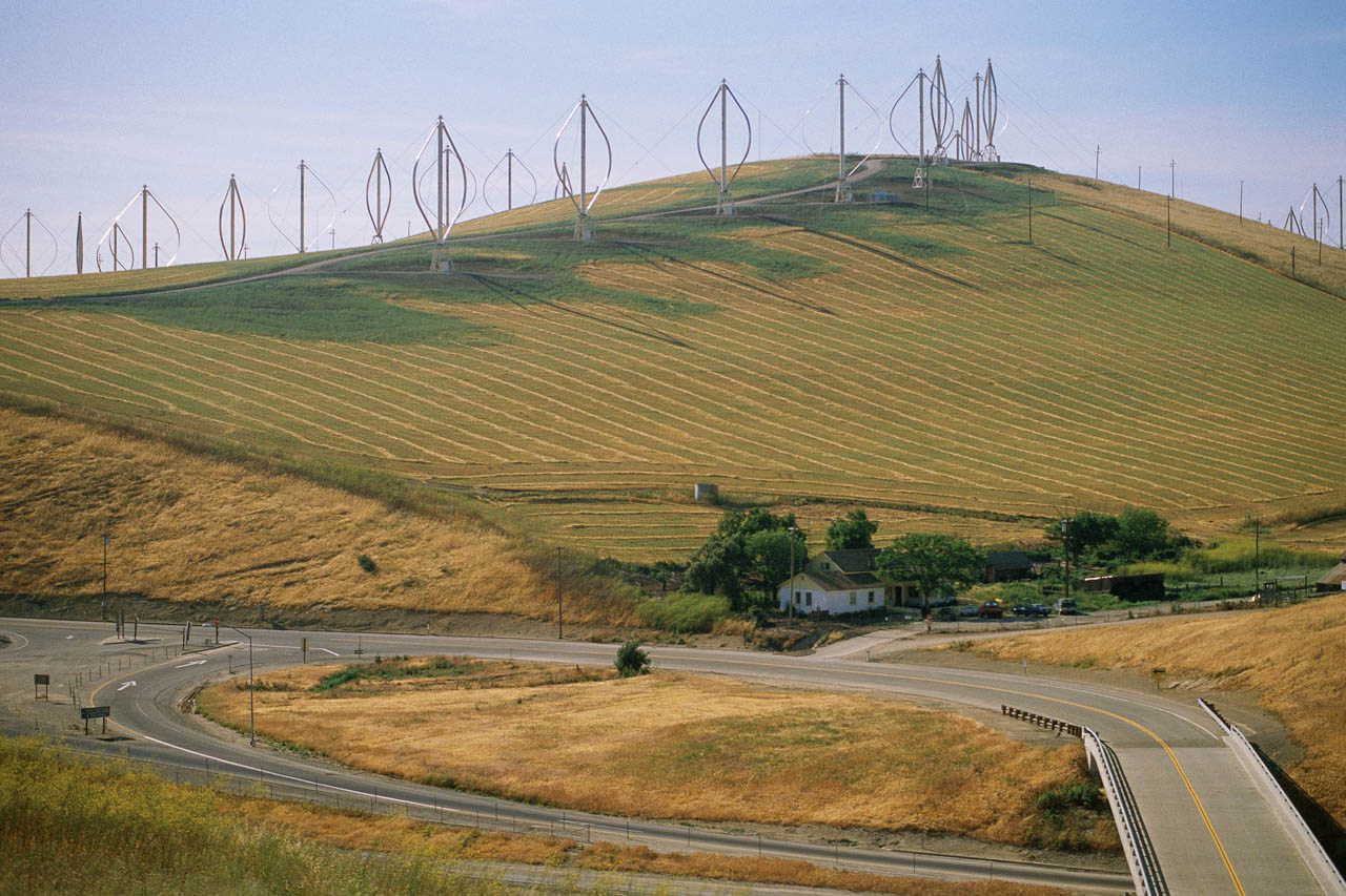
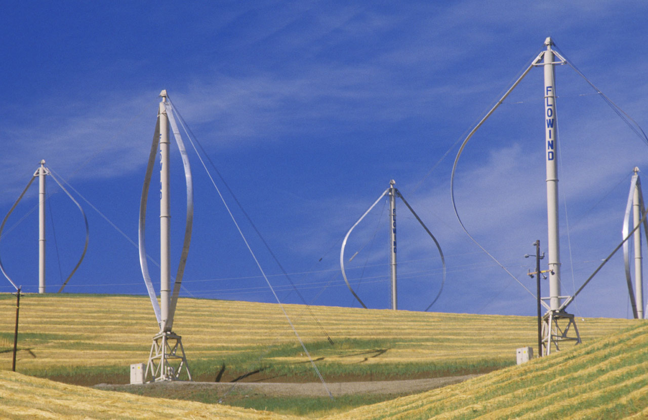
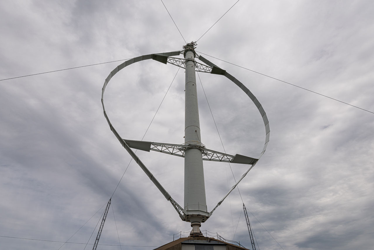
This vertical turbine was invented by the French engineer Georges Jean Marie Darrieus. The turbine usually consists of two or three aerofoil blades that rotate around a vertical axis creating a cylindrical, spherical or parabolic surface. Since blade speeds are many times faster than the wind speed, Darrieus turbines are considered high speed wind engines. That imposes high requirements on the blade material and the mounting of the blades since high centrifugal forces are involved.
Darrieus Turbines are independent of the wind direction and they can reach an efficiency of 35%. They exploit the lift principle to extract energy from the wind. Aerofoil blades rotate at a zero rigging angle in the flowing air circumscribing a circle around the rotor axis. The relative airspeed of the oncoming air resulting from the circling motion of the aerofoil is added vectorially to the speed of the wind. The resultant airflow then creates a small angle of attack on the aerofoil which produces lift. This force is directed into the turbine, past its axis, and creates torque which makes the turbine turn.
One of the variants of the Darrieus turbine is the one with an H shaped rotor. It is easier to manufacture since the aerofoils are straight but the mounting must be stronger due to the significant centrifugal forces. To avoid pulsation, Darrieus wind turbines often use spiral blades which makes it possible to evenly distribute the torque.


The working principle of a Darrieus turbine.
Free Downloads › Images
The advantages of Darrieus turbines are: their easy maintenance (as all mechanic parts are near the ground) and there is no need for a mechanism to turn the turbine into the wind as it is almost independent of its direction. On the other hand, an external power source is needed to start the turbine spinning. Further disadvantages are the difficulty of control, a pulsating output cycle that leads to resonance, and very high centrifugal forces in the rotor. Due to these facts, the dynamic strain on these turbines is much higher than the strain on horizontal axis turbines which means that Darrieus turbines have a shorter life span.
8 pictures
8 pictures
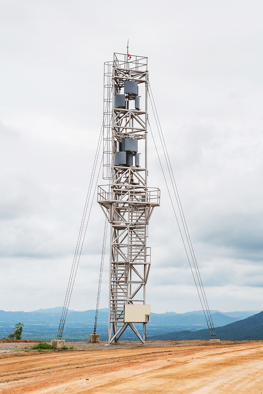
Vertical Savonius Wind Turbine
Video: 3D model of Savonius turbine.
Free Downloads › Animations
The Savonius turbine is one of the simplest turbine designs. It was invented by Sigurd J. Savonius from Finland in 1922. This turbine uses drag to extract energy from the wind and it falls into the category of low speed wind engines since the speed of the blades never exceeds the speed of the wind (it has a tip speed ratio < 1). The efficiency is usually around 20%.
The turbine consists of two joined half-cylindrical scoops attached to the vertical axis, which, seen from above, form a shape similar to the letter S. Due to the different drag ratio of the concave and convex surfaces of the scoops, a much larger force acts upon the concave surface (blade) and thereby makes the turbine rotor turn. The axis of rotation is perpendicular to the direction of the wind. The inner rims of the blades at the centre of the rotor overlap, allowing wind to pass through. The Savonius turbine rotor revolves relatively slowly but has a high torque. These characteristics predetermine the primary purpose of this turbine to drive water pumps or grind grain rather than produce electricity. Still, some household generators are driven by this type of turbine. They are not too efficient and are generally used in places with strong turbulent air currents.
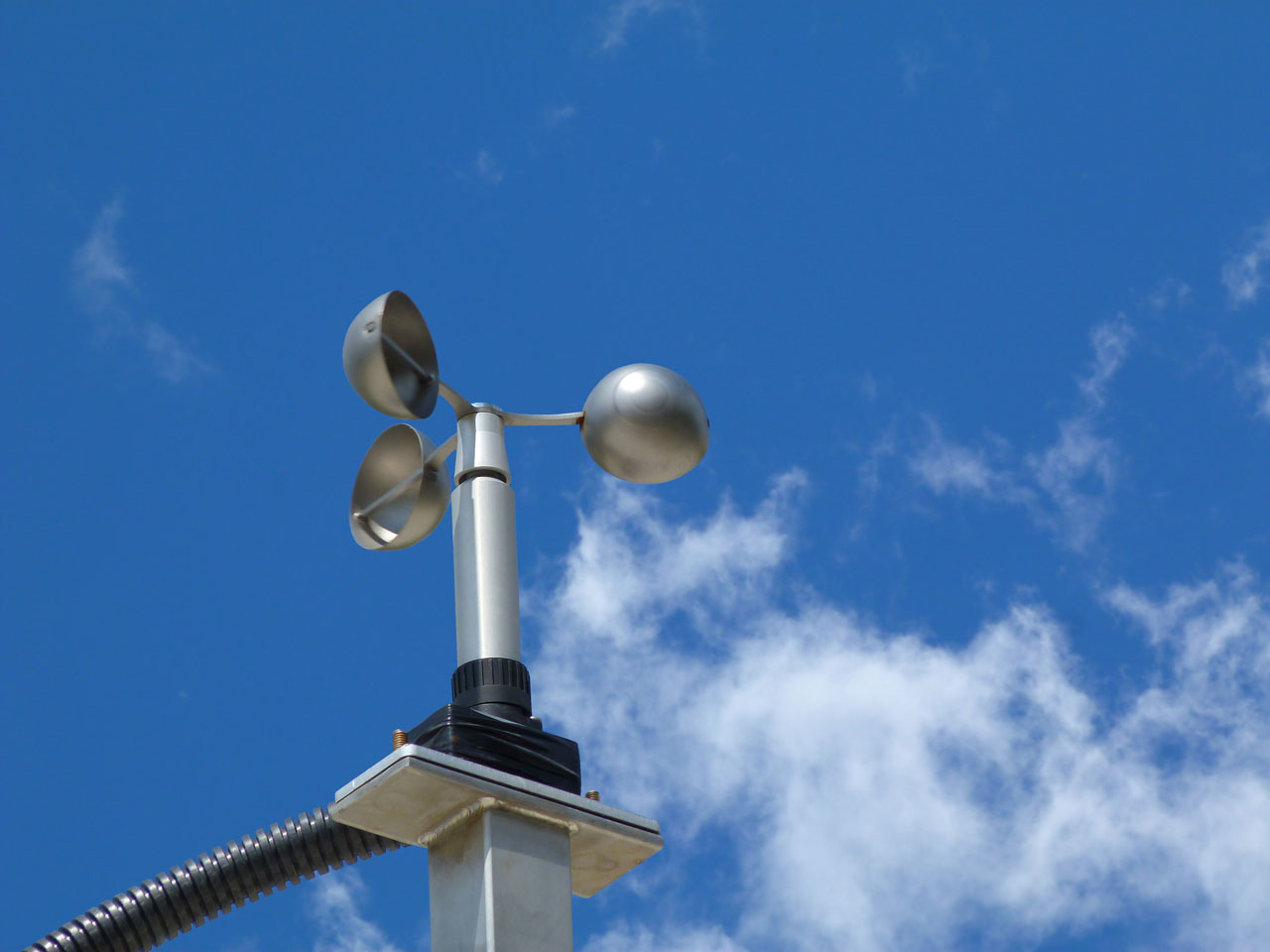
Another disadvantage of two-bladed Savonius turbines is that they have a dead angle. When wind blows from this angle the turbine will not start turning on its own. Ways to resolve this are to use screw shaped blades or joining several turbines on one axis, each with the blades at a different position. In meteorology, some anemometers (for measuring wind speed) are based on the principle of the Savonius turbine.

The working principle of a Savonius turbine.
Free Downloads › Images

6 pictures
6 pictures
Wind Turbine Efficiency Graph
 is the ratio between the circumferential speed of the tips of the blades and the speed of the wind.")
The tip speed ratio λ (lambda) is the ratio between the circumferential speed of the tips of the blades and the speed of the wind.
Free Downloads › Images
