
Solar Energy and Solar Power Systems Summary
34 min read
 can be observed on the surface of the Sun. (Source: © muratart / stock.adobe.com)")
Protuberances (enormous clouds of plasma ejected into the surroundings) can be observed on the surface of the Sun.
The thermonuclear fusion reactions continuously taking place in the Sun represent an immense source of energy. Although only a tiny fraction of this energy — about 45 billionths — reaches the Earth, it can be harnessed by various types of solar power technologies that operate either by concentrating sunlight and absorbing thermal energy or by directly converting solar radiation into electricity.
Energy of Solar Radiation

A concise overview of the six fundamental layers of the Sun, each differing in thickness, temperature, pressure, and chemical composition.
Free Downloads › Images
The Sun is a celestial body — a colossal plasma sphere — with an average density slightly higher than that of water. Within its core, ongoing nuclear fusion causes four protons to gradually combine into a single helium nucleus, releasing an enormous amount of energy.
A comparison of the masses of protons and helium shows that roughly 0.7% of the original proton mass is converted into energy. This energy is initially carried away by high-energy gamma-ray photons produced in the reaction. Through repeated interactions with other particles, these photons heat the inner layers of the Sun. The energy is then transported outward by convection through several layers until it reaches the photosphere, the Sun’s visible surface, from which it is emitted as solar radiation. The photosphere is observed from Earth as the familiar solar disc.

Ratio of solar radiation components that are incident on the Earth.
Free Downloads › Images
Over its lifetime of about 4.6 billion years, the Sun has already consumed roughly half of its hydrogen reserves — an immense amount, considering that the fusion reactions convert approximately 700 million tonnes of hydrogen every second, of which about 5 million tonnes are transformed directly into energy.
Only a small fraction of the Sun’s radiated energy reaches Earth in the form of solar radiation. About one third of the incoming radiation is reflected back into space, around one fifth is absorbed by the atmosphere, and slightly more than half is absorbed by the Earth’s landmasses and oceans.
")
Variations in solar irradiance throughout the 11-year solar cycle. (You can download the solar radiation variation chart in the Free Downloads section)
Free Downloads › Images
The Earth’s atmosphere filters part of the solar radiation, allowing primarily visible light and portions of ultraviolet (UV) and infrared (IR) radiation to reach the surface. The amount of solar energy that falls on a unit area (1 m2) perpendicular to the Sun’s rays per unit time (1 s) is referred to as solar irradiance.
If this surface is placed outside the Earth’s atmosphere, at a distance of one astronomical unit (the average Earth-Sun distance), the resulting solar irradiance is known as the solar constant. Its value is approximately 1,367 W/m2, varying by a few tenths of a percent depending on the Sun’s activity within its 11-year solar cycle.

Methods of using Solar Heat
The utilisation of solar thermal energy has been known since ancient times. Proper orientation of buildings and the application of solar architectural elements laid the experimental foundations for passive solar systems. The invention of flat glass further expanded the use of greenhouses and botanical gardens.

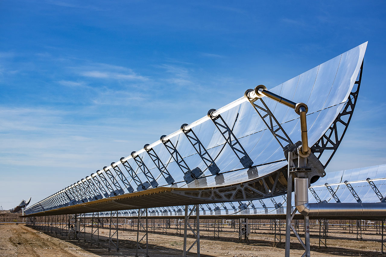
Parabolic trough concentrated solar power technology principle.
It was not until the second half of the 19th century that experiments with the technical use of solar energy began. The French teacher Augustin Mouchot constructed the first steam engine powered exclusively by solar energy, and a few years later, the first parabolic trough collector appeared.
The first solar thermal power plant using parabolic trough collectors was built in 1913 in Meadi, Egypt, by the American engineer Frank Shuman. The facility powered a water pump drawing water from the Nile for irrigation purposes. The same principle — a parabolic trough focusing sunlight onto a receiver tube containing a heat transfer medium — was later used in the SEGS (Solar Energy Generating Systems) plants built in California’s Mojave Desert.
Passive Solar Systems
")
A glazed wall in a hallway of a residential house — a passive element in solar architecture.
The simplest way to harness solar radiation is through passive solar systems integrated into building design. Apart from sunlight itself, they require no additional energy or mechanical components for their operation.
The inclusion of suitable passive architectural elements can significantly reduce a building’s energy demand, especially for heating. Most commonly, designs incorporate large glazed façades that utilise the greenhouse effect. Various passive solar solutions are frequently implemented in low-energy building designs.
Active Solar Systems
In contrast to passive systems, active solar systems employ various electromechanical components and processes to improve the absorption of solar radiation or the transfer of thermal energy. From a physical standpoint, active systems can be divided into two main categories:
- Solar Thermal Systems;
- Photovoltaic Systems.
")
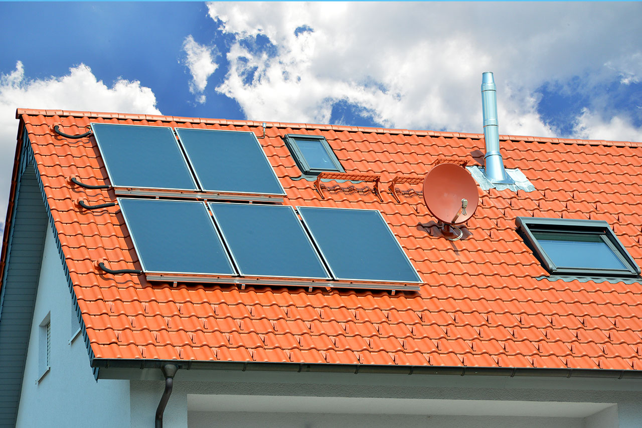
Active system of solar water heating.
The first category includes all technologies that use solar radiation to heat a heat transfer medium, which is then used to transport the thermal energy to the point of consumption. This group includes thermal collectors for space heating and domestic hot water production, where the absorber area equals the collector’s surface, as well as concentrating solar power (CSP) collectors, where the absorber area is much smaller than the total collector surface.
Typical active solar thermal systems consist of solar collectors that absorb solar energy, thermal storage units, heat exchangers, pumps, valves, piping, and intelligent electronic control systems. These systems can make a substantial contribution to meeting a household’s thermal energy demand.

The basis of every thermoelectric generator is a set of thermocouples connected in series, whose hot ends are heated by solar radiation.
The second category is characterised by the direct conversion of solar energy into electricity, without the involvement of moving mechanical parts or heat-transfer media. These are modern photovoltaic (PV) systems, valued for their simplicity, installation flexibility, and the ability to supply electricity on demand immediately after generation.
At the interface of both categories are thermoelectric generators. These devices use concentrated solar radiation to heat an absorber, but instead of a heat-transfer fluid, they contain the hot junctions of numerous interconnected bimetallic thermocouples. These thermocouples generate electricity based on the Seebeck effect, making this a form of indirect solar-to-electricity conversion.
Educational materials on the utilisation of solar energy — including videos, interactive lessons, and knowledge tests — are available in the Learning section.
Solar Energy Learning


Advantages of Solar Energy
One of the principal advantages of solar energy is its inexhaustibility. The Sun is the primary source of energy in our solar system, and the amount of solar radiation reaching the Earth is both substantial and relatively stable. Even large-scale utilisation of this renewable resource would have virtually no impact on the biological or energy balance of the natural environment.
")
Solar energy is virtually inexhaustible, and its use does not influence the energy balance in nature.
Another significant benefit is its environmental friendliness. The generation of solar energy does not depend on fuel supplies, produces no waste, and does not lead to the release of pollutants or greenhouse gases that could contribute to global warming or air pollution.
A further advantage of solar power is its low operating cost and minimal maintenance requirements. Although the initial installation cost of a solar system can be relatively high, the return on investment is typically ensured by the low running costs over the system’s operational lifetime. This is especially true for photovoltaic systems and solar thermal collectors. It is worth noting, however, that concentrating solar power (CSP) systems — which use large numbers of tracking mirrors and steam turbines — do require a higher level of maintenance.
Solar Collectors
")
Scheme of an air-based solar collector, illustrating its main components and operating principle.
Free Downloads › Images
The primary purpose of solar collectors is to heat a heat transfer medium, which then transports the collected heat to thermal storage units or points of direct consumption.
The simplest collector design is the air-based solar collector, in which air is heated directly. These are used mainly in ventilation and air-conditioning systems, and less frequently in space-heating systems. Due to the lower heat transfer efficiency between the absorber and air — and the lower specific heat capacity of air compared with liquid-based systems — achieving the desired energy output requires larger absorber surfaces and a higher airflow rate through the collector.
The absorbers in air collectors can either be directly exposed to solar radiation or enclosed within a collector frame and covered with a transparent layer, which reduces heat losses and improves the collector’s overall efficiency.
An interactive 3D model of a flat-plate solar collector for domestic water heating is available in the 3D Models section, or you can download the embed code for your own website from the Free Downloads section.
Online 3D Model › Energy Efficient House
Free Downloads › Online 3D › Energy Efficient House
Another type of solar thermal collector is the flat-plate collector. As the name suggests, it consists of a flat copper or aluminium plate coated with a black selective surface that enhances the absorption of diffuse solar radiation. The plate heats up through absorption and transfers the thermal energy by conduction to pipes containing the circulating heat transfer medium. To minimise heat losses, the flat absorber is insulated from the collector frame using standard insulating materials and covered with glass or a transparent plastic sheet.
Maximum performance of flat-plate collectors is achieved when they are optimally oriented and tilted. Ideally, the collector surface should always remain perpendicular to incoming sunlight, although a continuous tracking system would be too complex and costly for most applications. In practice, fixed installations are most common, with collectors facing south or south-west and tilted at about 50°, which is optimal for central European latitudes, especially during transitional seasons.
Flat-plate collectors are fundamental components of solar water-heating systems and, with efficiencies of 70—80%, can reduce water-heating costs by up to two-thirds.
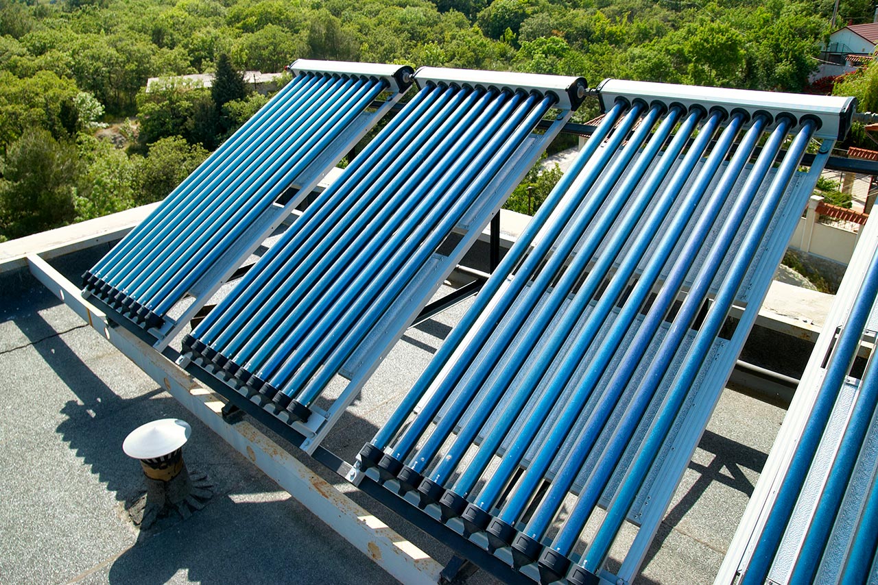
Due to the good insulating properties of vacuum, evacuated tube collectors reach better utilization of solar radiation than other types of solar thermal collectors.
Free Downloads › Animations
Evacuated tube collectors achieve even higher efficiency than flat-plate collectors by using a vacuum as insulation.
From a design perspective, evacuated tube collectors may consist of a single vacuum-sealed tube or two concentric glass tubes with a vacuum between them. Heat removal from the absorber occurs either through the flow of the heat transfer medium via U-tubes or through heat pipes operating in a binary thermodynamic cycle.
A heat pipe is a hermetically sealed tube containing a working fluid with a low boiling point. When heated, the fluid evaporates and the vapour rises to the condensation zone in the upper part of the tube. There, it condenses, releasing its latent heat to the heat transfer medium. The condensed liquid then flows back down to the lower part of the tube by gravity, completing the cycle.
In single-tube evacuated collectors, a flat absorber with a selective coating is located inside a single vacuum-sealed glass tube and is thermally connected to a metal tube. The seal between the metal and glass must be extremely tight to prevent degradation of the vacuum over time.
An interactive 3D model of an evacuated tube solar collector for water heating can be viewed online in the 3D Models section, or you can download the embed code from the Free Downloads section.
Online 3D Model › Energy Efficient House
Free Downloads › Online 3D › Energy Efficient House
A double-tube evacuated collector (one tube nested inside another) operates on a principle similar to that of a thermos flask — the vacuum space between the tubes minimises heat loss from the absorber. Solar radiation passes through the outer glass tube and is absorbed by a selective surface on the inner tube. The captured solar energy is then transferred by conduction to an aluminium fin in contact with a copper tube or a heat pipe in the non-vacuum central section.
When heat pipes are used, their condensing ends are inserted into a copper manifold, where the heat is transferred to the flowing heat transfer medium.
Solar Concentrators
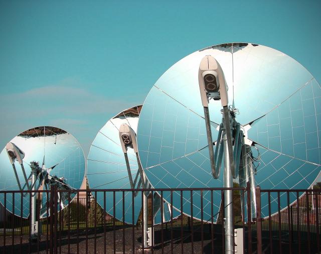
A parabolic dish concentrator is a large-scale solar collector that focuses all incoming solar radiation onto a single point — the focus of the parabola — where the absorber is located. By concentrating radiation from a large surface area, temperatures of up to 1,000 °C can be achieved at the collector’s focal point.
Manufacturing a precise parabolic mirror several metres in diameter is technologically challenging. For this reason, larger concentrators are typically composed of numerous smaller mirrors arranged on a supporting structure to form the overall parabolic surface.
3D model of Parabolic Dish Concentrator with Stirling engine.
Free Downloads › Animations
The complexity of the design also stems from the need to support not only the heavy mirrors themselves but also the receiver assembly, since the absorber must track the Sun’s movement along with the parabola.
In most solar concentrator power systems, the focal point contains the absorber of a Stirling engine, which uses the concentrated heat as its energy source. The output of individual units is typically in the range of tens of kilowatts, so solar power plants often deploy dozens or even hundreds of parabolic concentrators operating together. Due to the moving components involved, these systems generally require more intensive maintenance.
Central Tower Solar Power Plants
An interactive 3D model of a central tower solar power plant can be viewed online in the 3D Models section or downloaded as an embed code from Free Downloads.
Online 3D Model › Solar Power Plant
Free Downloads › Online 3D › Solar Power Plant
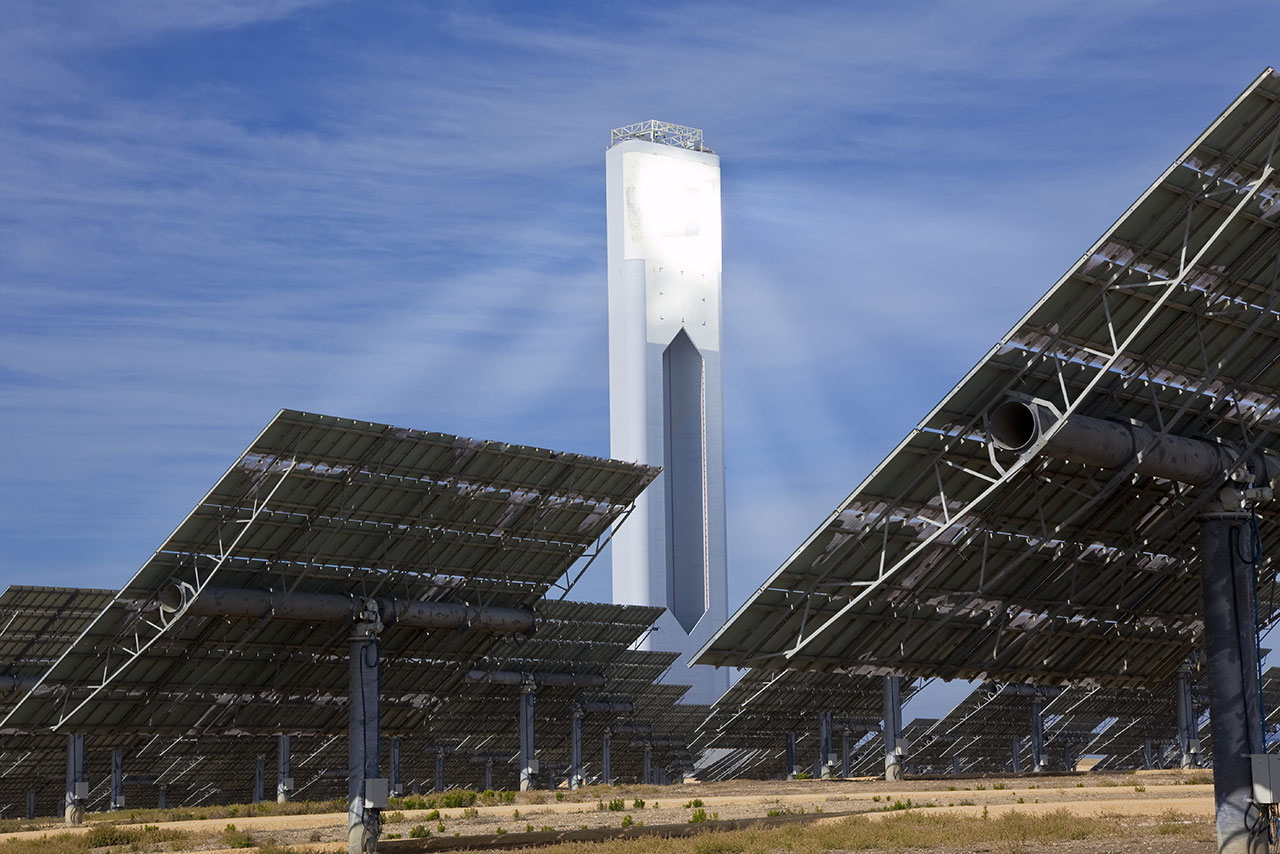
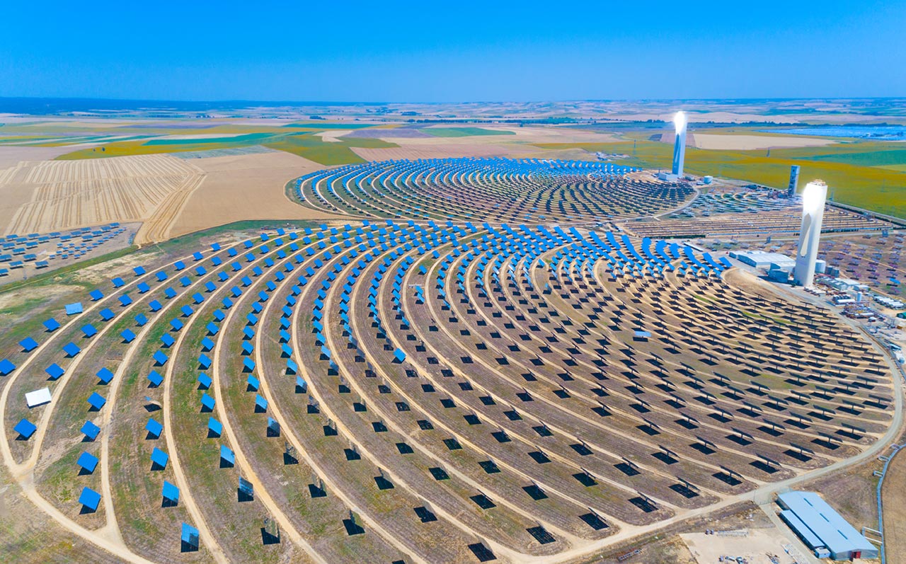
Central tower solar power plants are another type of solar concentrator system. Unlike parabolic concentrators — which move the entire mirror assembly as one unit — these systems use a large number of independently controlled flat mirrors, known as heliostats, positioned around a central tower containing the absorber. Each heliostat tracks the Sun individually, continuously reflecting and focusing sunlight onto a small area at the top of the tower.
The heat captured by the absorber is transferred via a heat transfer medium — such as water, oil, or molten salts — to the plant’s power conversion system, where it is converted into electricity using a conventional steam cycle. Because of the high concentration of solar energy, the absorber reaches temperatures typically above 500 °C, which significantly enhances the overall efficiency of the power plant.

2D diagrams of a central tower solar power plant.
Free Downloads › Images
The entire power conversion system is usually located at the base of the tower or in an adjacent engine room. In some installations, thermal energy storage units are also included, enabling electricity generation after sunset or during adverse weather conditions.
Among the pioneering examples of central tower solar power plants are the Solar One project in California’s Mojave Desert, with an installed capacity of 10 MW, and the Solar Tres Power Tower in Spain, with a capacity of 15 MW. Another notable facility is the PS20 power plant in Spain, which achieves a capacity of 20 MW.
Solar Farms

A 3D diagram of a parabolic trough solar power plant.
Free Downloads › Images
Solar farms are power plants that generate thermal energy from solar radiation using parabolic trough collectors. They belong to the broader category of solar concentrators, although in this case, the radiation is not focused into a single point as in central tower power plants. Instead, parabolic mirrors reflect incoming sunlight onto their focal line, through which a dark tubular absorber carrying a heat transfer medium is positioned.
The basic unit of a solar farm consists of a series of interconnected parabolic trough collectors. At one end of the series, the heat transfer fluid — usually a type of synthetic oil — is supplied into the absorber located at the focal line. At the opposite end, the heated fluid is directed to the plant’s power conversion system, where the captured thermal energy is either converted into electricity or utilised in industrial processes.
During the day, the control system rotates all the troughs so that they constantly reflect the sun’s rays into the focal point through which the absorber pipe passes.
Free Downloads › Animations
The total output of a solar farm essentially depends on the number of installed collector units.
The outlet temperature from the absorbers of parabolic trough collectors can reach up to 400 °C, and when high-quality mirror surfaces are used, thermal efficiencies of nearly 90% can be achieved. The most common configuration for trough collector arrays is north-south alignment, allowing the collectors to rotate along their longitudinal axis to track the Sun’s movement.
The largest solar thermal power facility using parabolic trough technology is the SEGS (Solar Energy Generating Systems) complex in California’s Mojave Desert, comprising nine units with a combined installed capacity of 354 MW. Other large solar farms have been built in Europe, North Africa, and the United Arab Emirates.
An interactive 3D model of a solar trough power plant with fluid flow animation can be viewed online in the 3D Models section or downloaded as an embed code from Free Downloads.
Online 3D Model › Solar Power Plant
Free Downloads › Online 3D › Solar Power Plant
A more cost-effective alternative to parabolic trough collectors is the use of linear flat mirror arrays based on the principle of a Fresnel lens. Each row of mirrors is mounted at a slightly different angle so that all mirrors reflect sunlight onto the underside of a fixed absorber positioned above them.
Inside the absorber tubes, water typically circulates and is heated to around 300 °C, where it vaporises directly. The resulting steam is then fed into a turbine in a conventional steam cycle.
Since flat mirror arrays are significantly cheaper to produce than parabolic mirrors, solar plants using Fresnel reflectors require lower investment costs compared to similarly rated parabolic systems.
Pioneering projects in Fresnel-based solar power generation include the Puerto Errado 1 plant in Spain, with an installed capacity of 1.4 MW, and the Kimberlina facility in California, which achieved a capacity of 5 MW.
The Largest Solar Power Plants
A set of interactive 3D models of different types of solar power plants can be explored online in the 3D Models section.
Online 3D Model
Free Downloads › Online 3D
Electricity generation in solar tower and solar farm power plants is based on heating a heat transfer medium to several hundred degrees Celsius and using the captured heat to generate electricity via a conventional Rankine cycle. The core of this cycle is a superheated steam turbine driving an electric generator.
One drawback, particularly for installations in desert environments, is the need for effective cooling. In the case of water-based cooling systems, solar thermal power plants require approximately 3 m3 of water per megawatt-hour (MWh) of electricity produced.
The method by which a solar power plant is integrated into the electrical grid depends primarily on the turbine’s capacity and the thermal storage system.
")
The largest solar power plants consist of a truly enormous number of long rows of trough collectors.
All of the world’s largest solar thermal power plants are based on parabolic trough technology. The largest is the SEGS (Solar Energy Generating Systems) complex in California’s Mojave Desert, with a total installed capacity of 354 MW. Other major facilities include the Solnova, Andasol, and Extresol plants in Spain, with installed capacities of 150 MW, 100 MW, and 100 MW, respectively. The fifth-largest facility is the Martin Next Generation Solar Energy Center in Florida.
Educational materials on electricity generation in solar thermal and photovoltaic power plants, including interactive lessons and knowledge tests, are available in the Learning section.
Solar Power Plants Learning


Energy Use of the Photovoltaic Effect

The photovoltaic effect is a physical process in which electromotive voltage is generated in a material exposed to radiation of a specific wavelength. In the case of photovoltaic cells, the material is most commonly a semiconductor, typically silicon, and the radiation consists of a stream of photons capable of dislodging free electrons from the silicon crystal lattice.
The condition of a specific wavelength means that a minimum photon energy is required for the electron release process to occur. This threshold energy is 1.12 eV, which corresponds to a wavelength of 1,105 nm. Photons with higher energy are absorbed and release electrons, whereas photons with lower energy cannot initiate the process.
The released electrons become free charge carriers within the material. Simultaneously, the absence of an electron at the original site creates a hole, which behaves as a positively charged particle. The existence of these electron-hole pairs makes it possible to generate electromotive voltage and thus produce an electric current.
")
Each photovoltaic cell consists of several layers, terminated on both sides by a grid of conductive contacts.
A photovoltaic cell is essentially a diode, composed of two layers of semiconductor materials forming an electric potential via a so-called P-N junction. The P-layer is most commonly made of crystalline silicon doped with boron (creating a surplus of holes), while the N-layer is silicon doped with indium (providing a surplus of free electrons). At the interface of these layers, a unidirectional barrier is formed, allowing electrons to pass only from the P-layer to the N-layer.
Electrons accumulate in the n-layer, creating an electric potential difference of about 0.6 V between the layers. When suitable electrodes are connected, this potential can be used to generate electric current.
Types of Solar Cells
")
Cheaper polycrystalline photovoltaic cells are made from a material composed of small silicon crystals.
At present, the most widely used types of solar cells are monocrystalline, polycrystalline, and thin film.
Monocrystalline solar cells offer the highest efficiency (14—20%) and are produced from thin, dark wafers cut from a single-crystal silicon ingot. Although they are more expensive, they are highly efficient and have a long service life.
Polycrystalline solar cells are a cheaper alternative with lower efficiency (12—15%) but are easier to manufacture. They are made from silicon composed of multiple small crystals. Their dark blue, usually square wafers display visible crystal boundaries.
Thin-film solar cells are characterised by flexibility, low production cost, and the lowest efficiency (below 10%). They are produced by depositing a thin layer of photosensitive material (such as amorphous silicon) onto a glass, plastic, or stainless-steel substrate. These cells are less sensitive to orientation and temperature and perform well even under low-light conditions.
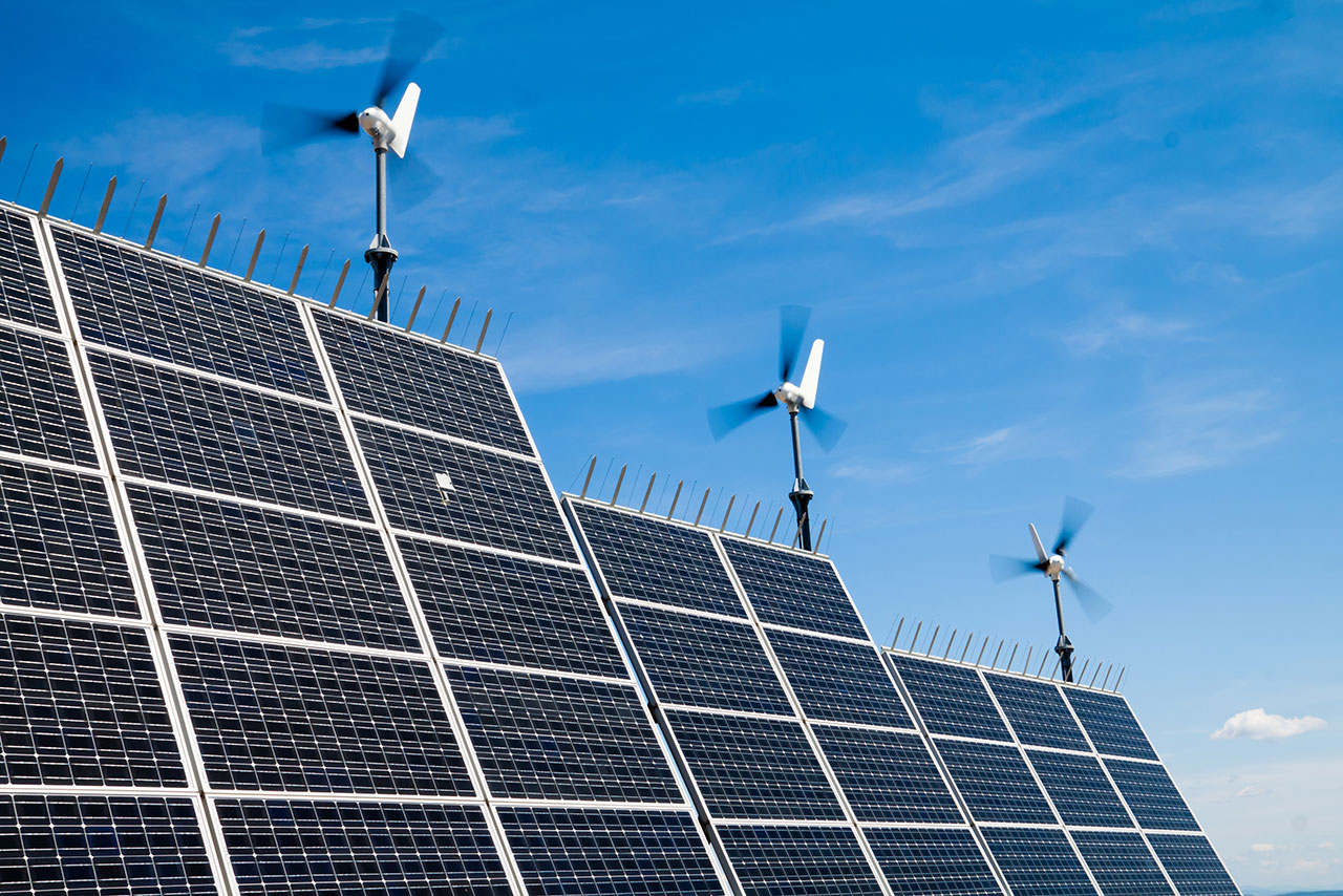
Photovoltaic Panels
Solar photovoltaic panel structure. An interactive 3D model of a solar panel is available online in the 3D Models section or as an embed code in the Free Downloads section.
Online 3D Model › Energy Efficient House
Free Downloads › Online 3D › Energy Efficient House
Individual solar cells are too small for practical use, so they are combined into larger assemblies known as solar panels. Cells are connected in series or parallel within the panel to produce electricity at a specific voltage, typically 12 V or 24 V. While the voltage is defined by the circuit configuration, the current output is directly proportional to the amount of light falling on the panel.
Structurally, a photovoltaic panel consists of a support plate onto which the solar cells are mounted, and a transparent top cover, usually made of tempered glass. The entire assembly is enclosed within an aluminium frame.

If desired, 3D-printable data for constructing a photovoltaic panel mounting stand can be downloaded from …
Free Downloads › 3D Printing
Free Downloads › Animations
Solar panels are most commonly installed on the roofs of residential and industrial buildings, but they can also be mounted on simple ground-based support structures suitable for installation in virtually any location.
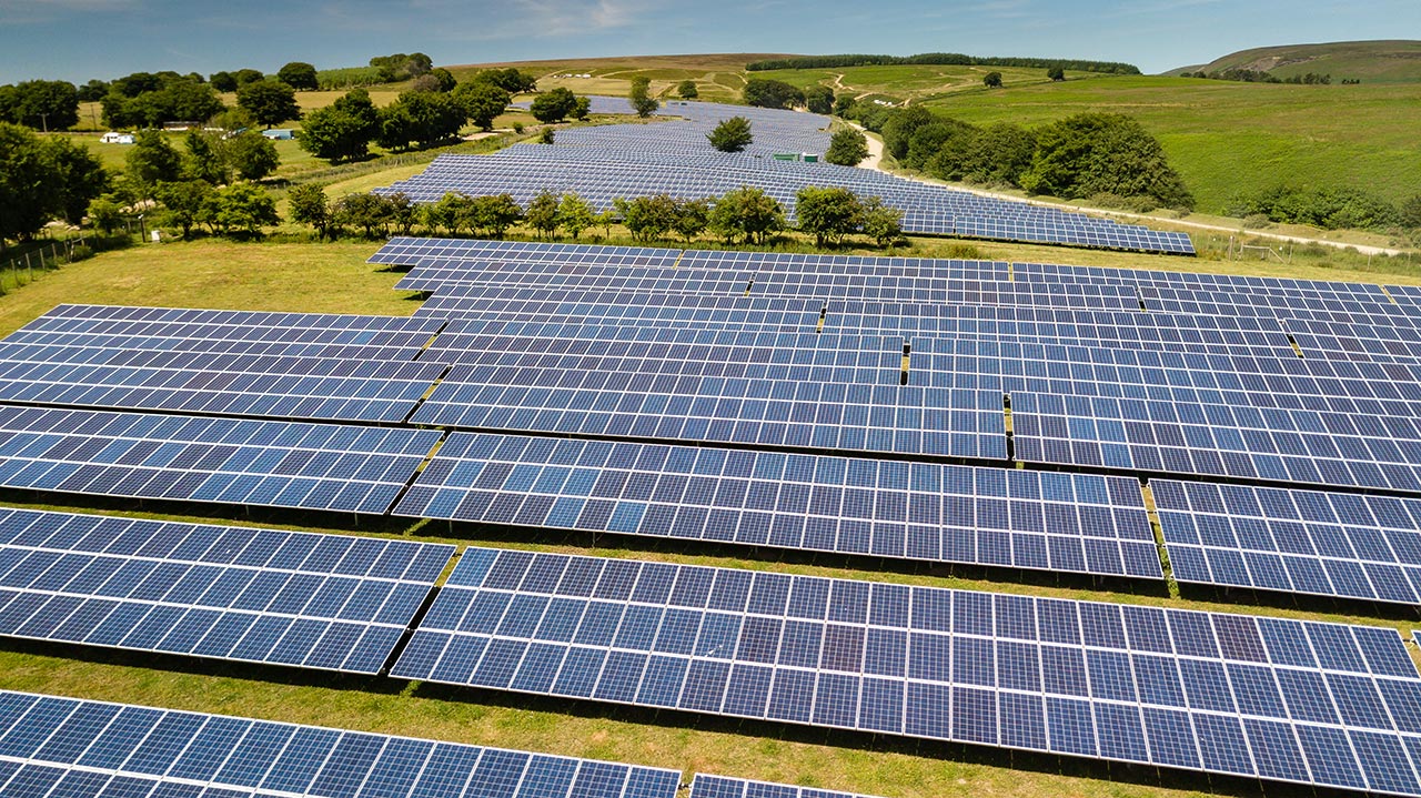
Photovoltaic Farms

A schematic diagram of a photovoltaic power plant.
Free Downloads › Images
A photovoltaic farm is created by installing a large number of solar panels in a single location. Because the average power density of modern commercial solar farms is only about 140 watts per square metre, such installations require extensive surface areas.
For grid compatibility, photovoltaic farms must be equipped with inverters and power transformers. The solar panels are typically mounted on simple, robust support structures, and solar tracking systems — which adjust panel orientation to follow the Sun — are rarely used due to their added complexity and cost.
An interactive 3D model of a photovoltaic power plant consisting of multiple solar panel arrays can be viewed online in the 3D Models section or downloaded as an embed code from Free Downloads.
Online 3D Model › Solar Power Plant
Free Downloads › Online 3D › Solar Power Plant
Photovoltaic systems are generally classified according to their installed capacity:
- Small-scale solar plants produce peak power in the range of tens of kilowatts (kW);
- Large-scale photovoltaic farms have installed capacities of several megawatts (MW) or even tens of megawatts.
The electricity generated is usually fed directly into the power grid, with the exception of standalone (off grid) photovoltaic systems, in which the generated energy is stored in batteries. These batteries then supply power to devices and infrastructure, for example, in remote areas without access to the central grid.
Most photovoltaic farms are located in Europe, although significant development is also underway in the United States, Japan, and Australia.
Solar Energy and the Environment
A video comparing various types of renewable energy sources can also be found in the Free Downloads / Videos section.
Free Downloads › Videos
The environmental impact of constructing and operating solar power plants is minimal. Although solar thermal power plants use the same basic principle of converting heat into electricity as conventional fossil-fuel or nuclear power plants, they do not involve combustion. As a result, they emit no pollutants or greenhouse gases into the atmosphere and produce no waste.
Similarly, photovoltaic power plants require no fuel or working fluids for their operation and generate electricity without emissions or waste. The only notable environmental drawback is the energy-intensive manufacturing of solar panels — a process that still relies partly on fossil fuels.
The environmental compatibility of solar energy has already been well demonstrated, and combined with its virtually inexhaustible primary source, it is considered one of the most promising technologies for future energy generation.
Development of Solar Energy
")
Building Integrated Photovoltaic is a new trend in the buildings construction where solar panels directly create roof or walls of the building.
Given the enormous potential of solar energy and the growing global trend of installing solar systems for both thermal energy and, above all, electricity generation, the future development of solar power is both inevitable and highly anticipated. This development will follow two main directions:
- The construction of large-scale solar power plants covering many square kilometres;
- The widespread integration of solar panels into various forms of infrastructure.
Significant attention is being given to concentrated photovoltaic (CPV) systems, which can achieve twice the efficiency of conventional photovoltaic farms of equivalent area. Plans are also underway for the construction of numerous solar thermal power plants in the Sahara Desert, complemented by a network of direct current (DC) transmission lines to deliver the generated electricity to consumption centres, such as those in Europe. In addition to these promising and well-established tower and trough-based solar plants, the region could also host solar updraft tower concepts — simple structures that use rising heated air to drive turbines and generate electricity.
")
In the future, wireless transmission of electricity from a space-based solar power plant to Earth is expected to be possible via a concentrated microwave beam.
The ambitions of photovoltaic technology reach even further. A major space-based solar power project is being considered, which would exploit the continuous availability of solar radiation at the level of the solar constant — 24 hours a day. The main challenge lies in finding an economically viable method for transporting solar panels into orbit and transmitting the generated electricity back to Earth.
