Nuclear Fusion Summary
55 min read
Thermonuclear Fusion — What It Is
Thermonuclear fusion is the fundamental nuclear process in which light atomic nuclei combine to form heavier nuclei, releasing vast amounts of energy in the process. It is the mechanism that powers stars, including our Sun, and represents a potential future source of virtually inexhaustible, low-carbon energy for humanity. Unlike nuclear fission, which splits heavy nuclei, fusion relies on overcoming the Coulomb repulsion between positively charged nuclei so they can merge under conditions of extreme temperature and pressure.
")
The curve shows that energy can be released by fusing light nuclei or by splitting very heavy ones. The maximum binding energy per nucleon occurs near iron, indicating the most stable nuclei.
The energy released in fusion originates from the nuclear binding energy curve. Lighter elements, such as hydrogen and its isotopes, have lower binding energy per nucleon than heavier nuclei like iron. When light nuclei fuse to form heavier ones, the resulting nucleus is more tightly bound, and the difference in binding energy is emitted, primarily as kinetic energy of particles and radiation.
Fusion reactions convert mass directly into energy, following Einstein’s mass-energy equivalence E = mc2. Even a minute mass difference between reactants and products results in enormous energy release. For example, the fusion of deuterium (2H) and tritium (3H) produces helium-4 (4He) and a high-energy neutron, releasing about 17.6 MeV of energy per reaction.
How Thermonuclear Fusion Works?
")
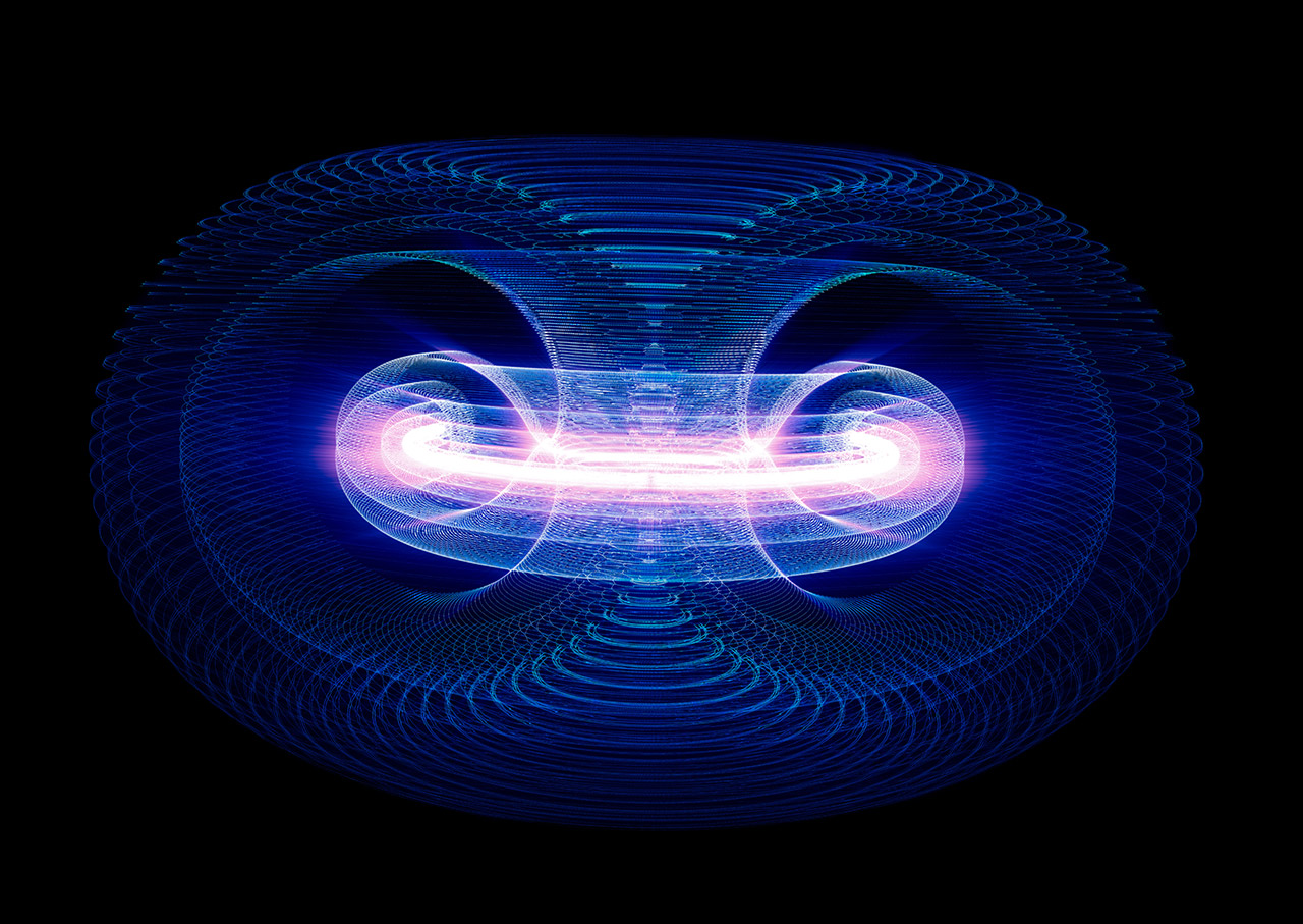
When a gaseous fuel is heated in a tokamak, some electrons are freed from their atoms and the gas becomes a plasma — the fourth state of matter.
For fusion to occur, two positively charged atomic nuclei must overcome their mutual electrostatic repulsion (Coulomb barrier) and come close enough for the strong nuclear force to bind them together. In practice, this is achieved by imparting very high velocities (i.e. extremely high temperatures) to the nuclei, so their inertia carries them past repulsive forces, combined with compressing matter to increase collision probability. For terrestrial fusion, the deuterium-tritium reaction is preferred, requiring ignition temperatures on the order of 150 million K.
Compression and heating often occur simultaneously: as matter is compressed it heats, and high density boosts interaction rates. In stars, gravity provides compression, whereas in artificial fusion devices compression may be driven by shock waves, or magnetic fields.
At such temperatures, matter exists as a plasma — a hot, ionised gas consisting of nuclei and electrons. The product of particle density, temperature, and confinement time determines whether a plasma can sustain net fusion energy production.

Eight nuclear fusion reactions with fusion products and energy yield.
Free Downloads › Images
Fusion Fuel
Fusion fuel selection is determined by reaction cross-section, energy yield, and fuel availability.
A practical fusion power plant will likely use D-T fuel initially due to its relatively low ignition temperature and high reaction rate. Deuterium – a naturally occurring stable isotope of hydrogen – is abundant and can be extracted from water, while tritium is slightly radioactive, rare and must be bred from lithium using neutrons produced in fusion reactions.
Other fuels, such as helium-3 and boron-11, offer lower neutron production and reduced radioactive activation but require more extreme conditions. Advanced fuel cycles may be explored in the future for improved safety and reduced waste.
Fusion in Stars
In stellar environments, fusion occurs under immense gravitational pressure and at temperatures of millions of degrees. The primary fusion processes in stars are:
- Proton-Proton Chain: Dominant in stars like the Sun, fusing hydrogen into helium via a series of reactions involving deuterium, helium-3, and helium-4.
- CNO Cycle: Operates in heavier stars, using carbon, nitrogen, and oxygen as catalysts.
- Triple-Alpha Process: In older stars, helium nuclei fuse into carbon and heavier elements.
As a star ages, the density and temperature of its core gradually increase, enabling the fusion of progressively heavier elements. Since these subsequent fusion reactions no longer produce energy, sufficiently massive stars end this phase of their evolution in a cataclysmic event known as a supernova.
During this process, gravitational collapse compresses and heats the remnants of the stellar core, triggering explosive fusion reactions that generate a wide range of chemical elements. Vast portions of the star’s mass are then ejected into space.
Everything on Earth was once part of the core of a star, forged through the process of thermonuclear fusion.
The Lawson Criterion
 as a function of temperature for various fusion fuels.")
The graph shows the required fusion triple product (ne·Te·τE) as a function of temperature for various fusion fuels.
In 1955, engineer John D. Lawson formulated the conditions under which nuclear fusion could become economically viable. The Lawson criterion states that the product of plasma density, confinement time, and temperature must exceed a critical threshold.
The ratio of fusion energy produced to the energy required to sustain the reaction is known as the fusion energy gain factor, or Q. To achieve a self-sustaining reaction where Q ≥ 1, the plasma parameters must satisfy the relationship:
n × τ = f(T)
For the deuterium-tritium reaction, this condition can be expressed as n × τ > 1.5 × 10²⁰ s.m−3 at temperatures around 100 million K.
From the Lawson criterion follow two main approaches to achieving viable fusion: magnetic confinement and inertial confinement.
Plasma and Its Confinement
")
In inertial confinement, the fuel pellet is compressed and heated by powerful laser or particle beams, creating the extreme conditions necessary for fusion to occur.
Plasma, often referred to as the fourth state of matter, is a highly conductive, magnetically responsive medium of ions and electrons. Effective plasma confinement is essential for achieving the Lawson criterion. The two main approaches are:
Magnetic Confinement: Uses powerful magnetic fields to contain and shape plasma in devices such as tokamaks and stellarators. Tokamaks use toroidal and poloidal fields to stabilise plasma, while stellarators employ complex field geometries for steady-state operation.
Inertial Confinement: Relies on rapid compression of a small fuel pellet using lasers or particle beams, achieving high densities and temperatures for very short durations.
Plasma stability is challenged by turbulence, instabilities, and heat losses through conduction and radiation. Advanced diagnostics and control systems are critical for monitoring and optimising confinement.
Plasma Diagnostics
Measuring plasma conditions in fusion devices is extremely challenging, since no instrument can survive direct insertion into the hot core. Diagnostics are therefore largely passive, observing emissions of particles or electromagnetic radiation, or active, probing plasma with microwaves, lasers or particle beams, with minimal perturbation.
)")
A precision magnetic field sensor used for steady-state field measurements on the outer structures of the ITER vacuum vessel.
Key diagnostic methods include:
Magnetic diagnostics: Detect plasma current, shape, and instabilities via induced voltages in coils or sensors.
Microwave diagnostics: Techniques include reflectometry, interferometry, polarimetry, electron cyclotron absorption, collective Thomson scattering and electron cyclotron emission.
Spectroscopy: In visible, UV and soft X-ray bands gives information on ion densities, temperatures, rotation, impurity composition. Also, bolometers, synchrotron radiation spectroscopy or beam emission spectroscopy is used.
Probes: Langmuir probes inserted into the plasma periphery measure electron temperature, density, potential, based on current-voltage curves.
Particle diagnostics: Analysis of particles escaping plasma — fusion products and impurity species.
All diagnostics must operate with high temporal resolution to track rapid plasma changes, and many provide only line-integrated data or local observations. To reconstruct full spatial and temporal profiles of temperature, density, and other plasma parameters, scientists combine multiple diagnostic techniques and apply complex computational algorithms.
Principles of Artificial Fusion
")
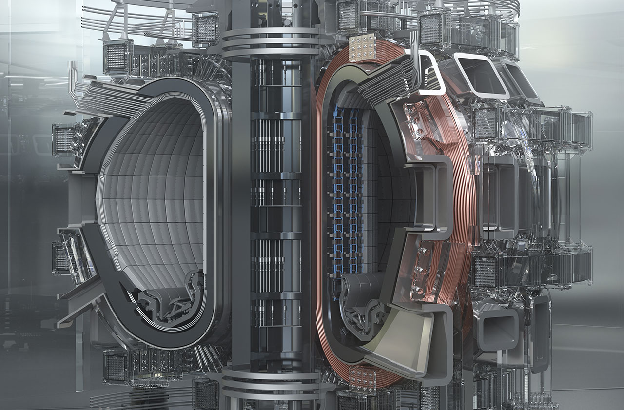
The tokamak is a typical and currently the most promising device based on magnetic confinement.
Replicating stellar fusion on Earth requires precise engineering and multidisciplinary expertise.
In magnetic confinement approach the plasma is hold in some kind of bottle made from magnetic fields while heating it to fusion temperatures. To prevent particles from escaping, magnetic traps or closed magnetic curves are used.
In inertial confinement approach the high-density plasma is confine for a short time. To reach fusion, pellets from fusion material is compressed in the hotspot from all sides by laser or electron/ion beam.
Alternative confinement strategies are explored in other concepts such as Spheromaks, Z-pinch devices or Fusor.
Achieving commercial fusion energy requires overcoming challenges such as plasma instabilities, material degradation under neutron bombardment, tritium breeding, and efficient energy capture. Nonetheless, steady progress in experimental facilities, materials science, and computational modelling continues to bring practical fusion power closer to reality.
Educational materials on the basic principles of thermonuclear fusion are available in the Learning section. You can explore video presentations and animated lectures that explain How Thermonuclear Fusion Works and how humanity is striving to harness this virtually limitless source of energy. Finally, you can test your knowledge through an interactive quiz.
How Does Thermonuclear Fusion Work? Learning


Main Principles of Tokamaks
An interactive 3D model of a tokamak can be viewed online in the 3D Models section or downloaded as an embed code from Free Downloads.
Online 3D Model › ITER Tokamak
Free Downloads › Online 3D
The term tokamak is derived from the Russian acronym ТОроидальная КАмера с МАгнитными Катушками, meaning toroidal chamber and magnetic coils. Tokamaks are by far the most developed magnetic confinement devices for thermonuclear fusion. The first operational tokamak, T-1 in the Soviet Union, began operation in 1958. Among all tokamaks to date, JET (Joint European Torus) is notable for having approached scientific breakeven in 1997 with a fusion gain of Q = 0.67. The largest tokamak currently under construction is ITER, located in Cadarache, France.
A tokamak confines plasma by means of strong magnetic fields arranged in a toroidal geometry. Charged particles (ions and electrons) spiral along the magnetic field lines, but a purely toroidal field is inherently inhomogeneous. In this case, particle drifts arise: electrons and ions migrate in opposite directions, causing charge separation. To counteract this effect, an electric current is driven through the plasma, generating a poloidal magnetic field that combines with the toroidal component to form helical field lines.

If desired, 3D-printable data for constructing a tokamak can be downloaded from the Free Download / 3D Printing section.
Free Downloads › 3D Printing
In this way, particles are trapped on nested magnetic surfaces, travelling once on the inner side and once on the outer, so the unwanted drift is cancelled and the particles remain confined within the vacuum vessel.
Initially, plasma heating is achieved by ohmic (Joule) heating via the induced current. As temperature increases and plasma resistivity decreases, additional external heating methods such as neutral beam injection and radiofrequency heating are employed to raise the temperature to fusion-relevant levels.
Thus, the tokamak is, in principle, a pulsed device, since the central solenoid drives a transient current in the plasma. The objective is to maintain adequate magnetic confinement, suppress instabilities, and minimise particle and energy losses.
Coil Materials & Magnetic Components
Since tokamaks require extremely strong magnetic fields, the selection of coil materials is critical. Superconductors are commonly used to minimise resistive heating and power losses, with niobium-titanium (NbTi) and niobium-tin (Nb₃Sn) being the most widely employed.
")
The central solenoid acts as the main transformer of the tokamak, inducing a powerful plasma current for heating and confinement control.
The toroidal field coils are typically arranged around the vacuum vessel, following its toroidal contour, like the rings on a doughnut. Poloidal field coils encircle the entire torus externally and provide the vertical (poloidal) magnetic component.
The central solenoid lies at the centre of the torus and acts as the primary transformer winding, inducing a toroidal current in the plasma. The large amount of energy required for a solenoid pulse is generally stored in an array of capacitor banks or flywheel generators.
In ITER, for instance, the central solenoid is a structure approximately 13 m tall and 4 m wide, capable of producing magnetic fields up to 13 tesla in the centre of its stacked modules. Because of the large electromagnetic stresses, strong supporting structures and robust mechanical design are essential.
Vacuum Chamber, Divertor & First Wall
")
The double-walled stainless-steel chamber confines the plasma and houses the blanket modules, divertor, and numerous diagnostic and access ports.
The vacuum vessel is the chamber in which the plasma is created, heated, and magnetically confined. It is constructed from stainless steel and lined on the inner side with first wall panels (replaceable tiles) made of refractory materials such as carbon, tungsten, or beryllium, designed to withstand intense heat fluxes and to minimise impurity contamination of the plasma. The vessel and the magnetic coils located behind it must be protected by neutron shielding, which absorbs high-energy neutrons produced by fusion reactions and converts their kinetic energy into heat that can be utilised for power generation. In large tokamaks, the combined thickness of the first wall and shielding (including neutron-absorbing and tritium-breeding layers) can reach up to 1.5 metres.
A divertor is a specialised region of the vessel, usually positioned at the bottom (or at another designated area), used to remove impurities and exhaust particles from the plasma. By shaping the magnetic field to direct the outer plasma flux lines toward divertor target plates, heavier ions and undesired particles are channelled away from the main plasma and pumped out of the vacuum chamber. The divertor plates experience extremely high thermal loads and must therefore be cooled and made from highly resilient materials such as tungsten or beryllium.
External Heating Methods
Although ohmic (resistive) heating by the induced plasma current is used initially, it becomes insufficient at higher temperatures because plasma resistivity decreases with increasing temperature. To reach fusion-relevant temperatures (approximately 100–150 million K), auxiliary external heating methods are employed.
 antennas are visible to the left of the central column. A new magnetic field-aligned ICRF antenna is visible to the right of the central column. (Source: Mike Garrett, Wikipedia.org)")
Interior of the Alcator C-Mod tokamak at the MIT Plasma Science and Fusion Center. Two Ion Cyclotron Range of Frequencies (ICRF) antennas are visible to the left of the central column. A new magnetic field-aligned ICRF antenna is visible to the right of the central column.
The principal systems include:
- Neutral Beam Injection (NBI): Ions (typically hydrogen or deuterium) are first accelerated to high energies and then neutralised before being injected into the plasma. Because the resulting atoms are uncharged, they can penetrate the magnetic field and transfer their energy to the plasma particles through collisions, thereby heating the plasma.
- Ion Cyclotron Resonance Heating (ICRH): Radiofrequency (RF) waves at ion cyclotron frequencies (tens of MHz) are used to heat the ions directly. The RF power is launched into the tokamak by large antenna structures, where the waves resonate with the ion cyclotron motion and thereby efficiently transfer energy to the plasma.
- Electron Cyclotron Resonance Heating (ECRH): High-frequency electromagnetic waves (hundreds of GHz) resonate with the cyclotron motion of electrons, increasing their kinetic energy, which is subsequently transferred to ions through collisions.
- Lower Hybrid Current Drive (LHCD): Radiofrequency waves in the lower-hybrid frequency range are used to drive a non-inductive current in the plasma, helping to sustain the plasma current even after the transformer-induced drive ceases.
Fuel for Tokamaks

Hydrogen has three isotopes: protium with no neutron, deuterium with one neutron, and tritium with two neutrons.
Without fusion reactions, obtaining fuel for tokamaks is straightforward — plasma can be created from hydrogen, deuterium, or helium. All of these gases are normally available in sufficient quantities, and moreover, fuel consumption in tokamaks is extremely low.
For fusion experiments, tokamaks commonly use a mixture of deuterium-tritium (D-T) fuel because of its relatively high reaction cross-section at achievable temperatures. Tritium must typically be bred in a surrounding lithium blanket using the neutrons produced by fusion reactions.
The fuel is usually injected into the vacuum vessel in the form of a gas. During operation, additional fuel can be supplied either as frozen pellets rapidly injected into the plasma or as small quantities of gas introduced at high velocity.
Problems & Challenges
")
Diffusion in a plasma occurs when the orbits of charged particles intersect, allowing them to drift across magnetic field lines.
Although tokamaks remain the most promising concept for achieving controlled thermonuclear fusion, they must still overcome a number of major technical and physical challenges.
Significant issues persist in several key areas: maintaining plasma volume and purity, mitigating turbulence and edge-localised modes (ELMs) in hot plasma, achieving stronger and more stable magnetic fields, ensuring continuous steady-state operation, and developing advanced materials capable of withstanding the extreme conditions within structural components.
Research on fusion in tokamaks is ongoing. Scientists have developed many models predicting how plasma should behave in large-volume devices; however, plasma often exhibits unexpected dynamics, and entirely new modes of behaviour may yet emerge as experiments progress.
Major Tokamaks & Milestones
")
The T-1 tokamak in the Soviet Union, the first device to carry the name “tokamak” and an early milestone in magnetic confinement research.
Since the first tokamak (T-1) in 1958, more than fifty tokamaks have been constructed worldwide. Early milestones include T-3, which in 1968 achieved temperatures of around 10 million K and demonstrated the tokamak concept to Western scientists, and the first use of external heating in the tokamak ORMAK in 1971.
A major breakthrough in overcoming turbulence and achieving the high-confinement mode (H-mode) occurred in 1982, while divertors had already become a common feature in tokamaks since the 1970s. In 1986, the Tokamak Fusion Test Reactor (TFTR) reached a plasma temperature of about 200 million K, setting a record for that time.
Prominent modern machines include JET in the United Kingdom, with a plasma volume of approximately 80 m³, which achieved its first plasma in 1983 and has since carried out many pioneering experiments using deuterium-tritium (D-T) fuel. Other important tokamaks include JT-60SA, EAST, WEST, and DIII-D. The next-generation device, ITER, currently under construction in Cadarache, France, aims to achieve a fusion gain of Q ≈ 10 and sustain long-pulse operation.
Historically, the “tokamak boom” of the 1970s led to a rapid expansion of tokamak research worldwide, while earlier alternative configurations such as pinch and stellarator devices gradually took a secondary role.
Educational materials on tokamaks are available in the Learning section. You can explore video presentations and animated lectures that introduce the working principles and construction of tokamaks, and finally test your knowledge through an interactive quiz.
Construction and Working Principle of Tokamaks Learning


Introduction to Stellarators
An interactive 3D model of a stellarator can be viewed online in the 3D Models section or downloaded as an embed code from Free Downloads.
Online 3D Model
Free Downloads › Online 3D
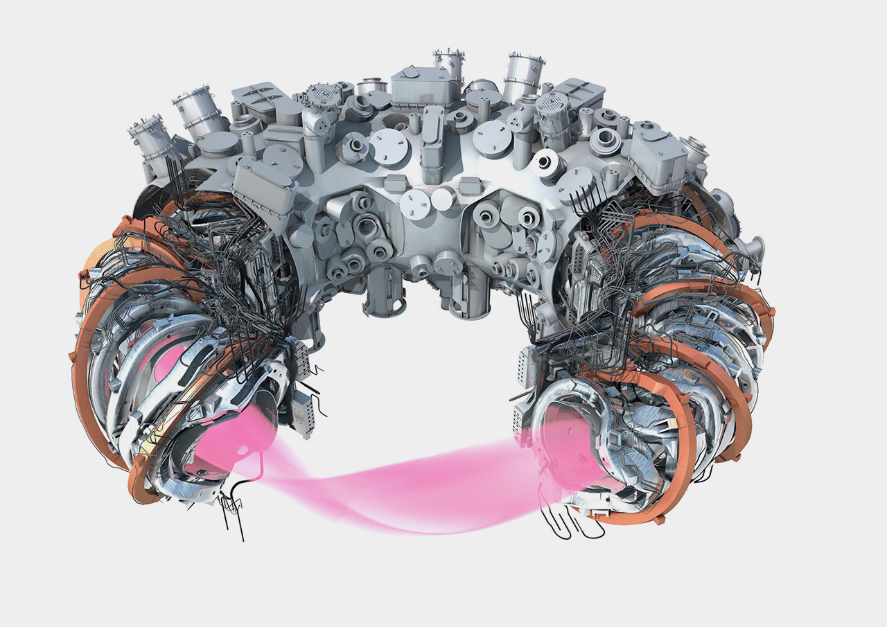
A stellarator is a type of magnetic confinement device for thermonuclear fusion in which the confining magnetic field is generated entirely by external coils — that is, without relying on a plasma current. The name derives from the idea of a “generator of stellar energy”. Stellarators offer the potential for continuous, steady-state operation, a key advantage over tokamaks, which operate in pulsed modes.
Historically, stellarators were developed before tokamaks, but interest declined until advances in computational power enabled the precise design and optimisation of their complex coil geometries. There are currently more than ten operational stellarators worldwide; the most prominent include Wendelstein 7-X (Germany), the Large Helical Device (Japan), and the Helically Symmetric Experiment (USA).

Classical stellarator schematic diagram. You can download it for your own projects from the Free Download / Images section.
Free Downloads › Images
The core principle of a stellarator is to create a helical magnetic field that confines plasma within a toroidal chamber, without relying on plasma current to generate the poloidal field component. In essence, the required rotational transform of the magnetic field lines is produced entirely by the shaping and positioning of external coils. Because there is no toroidal current flowing in the plasma, stellarators avoid many of the current-driven instabilities and disruptions characteristic of tokamaks.
Magnetic Coils
The external magnetic coils in stellarators are carefully engineered to generate the required three-dimensional magnetic field configuration that confines plasma in a toroidal shape. Unlike the coil systems of tokamaks, stellarator coils are non-planar and intricately three-dimensional, designed to produce both the toroidal and poloidal components of the magnetic field without relying on a plasma current.
")
Model of the TJ-II heliac, a flexible stellarator whose coil system allows wide variation of magnetic configurations.
Designing such coils is a major engineering challenge. The magnetic field must simultaneously provide sufficient confining strength, maintain high field quality with smooth magnetic surfaces, minimise field errors, and limit mechanical stress and construction complexity. Advances in computational modelling and optimisation techniques have made it possible to design coil geometries that achieve these goals.
The geometry of stellarator coils is inherently complex: to produce the necessary magnetic field, the coils must be contoured with extreme precision. The resulting field lines follow a helical path around the torus, forming closed magnetic surfaces that confine charged particles (ions and electrons) and minimise drift losses.
In modern large stellarators the coils are constructed from superconducting materials, allowing strong magnetic fields to be maintained continuously without resistive losses. This enables long-pulse or steady-state operation while significantly reducing power consumption and thermal stress on the coil system.
Vacuum Chamber & Divertor
")
Section of the Wendelstein 7-X vacuum vessel, showing the highly twisted geometry required to match the stellarator’s three-dimensional magnetic field structure.
Stellarators employ a vacuum vessel similar in function to those used in other magnetic confinement devices. The vessel, typically constructed from stainless steel, encloses the plasma and provides mechanical support for first wall components. Because of the twisted geometry of the magnetic field, the vessel itself must have an irregular, three-dimensional shape that closely follows the configuration of the plasma.
The inner surface is lined with resilient plasma-facing materials such as tungsten, beryllium, or carbon, which can withstand high heat fluxes and neutron bombardment while minimising impurity release into the plasma. Numerous diagnostic and access ports are integrated into the vessel walls, allowing for plasma measurements, heating systems, and maintenance access.
To manage impurities and exhaust heat and particles escaping from the plasma, stellarators are equipped with divertor or exhaust systems, conceptually similar to those used in tokamaks. These divertor units handle intense thermal loads and intercept stray particles and plasma fluxes that deviate from the core. They play a crucial role in controlling and limiting plasma-wall interaction and in protecting both the main plasma and the vessel walls.
Challenges & Limitations

A modular stellarator model depicting the plasma, vacuum chamber, modular coils and cryostat.
Free Downloads › Images
Although stellarators offer several inherent advantages, they also face a number of technical and physical limitations. The most significant challenge lies in the extremely complex coil geometry, which must generate the full magnetic configuration without relying on a plasma current. Even small inaccuracies in coil positioning can introduce magnetic field errors and degrade confinement. Stellarators also face issues with particle diffusion and transport.
Another major limitation is the engineering and cost complexity of constructing large-scale stellarators. Their intricate, non-planar coils and asymmetric vacuum vessels are difficult to manufacture, assemble, and maintain. Managing heat loads and particle fluxes on the first wall and divertor surfaces also presents challenges, as these components must withstand prolonged exposure to extreme conditions. Advances in computational optimisation, superconducting technology, and plasma diagnostics are steadily overcoming many of these limitations, bringing the stellarator concept closer to reactor-level performance.
Prominent Stellarators & Milestones
, showing the strongly twisted plasma vessel characteristic of helical stellarator geometry. (Credit: Wikimedia Commons)")
Interior of the Large Helical Device (LHD), showing the strongly twisted plasma vessel characteristic of helical stellarator geometry.
Several stellarators have demonstrated the viability of the concept and advanced the understanding of stellarator physics. Among the most notable are:
- Wendelstein 7-X (Germany) — one of the most advanced modern stellarators, designed to test long-pulse, steady-state operation and to demonstrate high magnetic field quality.
- Large Helical Device (LHD) (Japan) — a large helical stellarator conducting extensive experimental programmes on plasma confinement and stability.
- Helically Symmetric Experiment (HSX) (USA) — designed to explore quasi-symmetric magnetic configurations and to reduce neoclassical losses.
These machines have helped validate magnetic surface quality, improve plasma confinement in three-dimensional fields, and develop strategies for steady-state operation. As stellarator devices such as Wendelstein 7-X continue to expand operational limits, they stand as a promising alternative path toward practical fusion power.
Educational materials on stellarators are available in the Learning section. You can explore video presentations and animated lectures that introduce the construction and working principles of stellarators, and then test your knowledge through an interactive quiz.
Construction and Working Principle of Stellarator Learning


Introduction to Inertial Confinement Fusion

Four stages of D-T pellet compression during laser-driven fusion.
Free Downloads › Images
Inertial Confinement Fusion (ICF) is a fusion approach that seeks to compress and heat small fuel targets so rapidly that the fuel’s own inertia provides the brief confinement required for fusion reactions to occur. The process relies on achieving extremely high compression and temperature within nanoseconds, before the fuel has time to disassemble.
While ICF is conceptually elegant and permits very high fuel densities, it presents extreme physical and engineering challenges.
A typical ICF scheme employs a small spherical pellet containing a mixture of deuterium and tritium (D-T). Surrounding this fuel is a thin shell, or “ablator” (commonly made of plastic, glass, or beryllium), which is rapidly vaporised or ionised by an external driver such as lasers or X-rays.
As the outer layer of the capsule explodes outward (ablation), the reactive inward pressure drives the remaining shell inward, compressing the fuel core to extreme densities and temperatures. If the implosion is sufficiently symmetric and well timed, the hotspot ignites and thermonuclear burn occurs.
To reach ignition, the fuel must achieve densities hundreds to thousands of times greater than that of solid matter, reducing the need for long confinement times. In ICF, the effective confinement time is typically between 10−9 and 10−7 seconds — so the high density compensates for the extremely short confinement duration.
 gas, a frozen D-T solid-fuel layer, and an outer ablator layer. (Source: Wikipedia.org)")
Inertial confinement fusion fuel microcapsules are 2-millimeter-diameter. They contain a central reservoir of deuterium-tritium (D-T) gas, a frozen D-T solid-fuel layer, and an outer ablator layer.
There are two principal drive modalities:
- Direct drive: laser or particle beams are aimed directly at the pellet surface, heating and ablating it uniformly. This method requires exceptionally uniform illumination to avoid asymmetries and instabilities.
- Indirect drive: the pellet is mounted inside a hollow cavity (hohlraum) whose interior walls convert the laser pulses into X-rays, which then symmetrically irradiate the fuel capsule. Indirect drive helps smooth out illumination non-uniformities but reduces overall efficiency due to energy conversion losses.
The Lawson criterion concept also applies to inertial fusion, although in a somewhat different form. Because the confinement time is limited by particle inertia, achieving the required threshold demands extremely high densities and an exceptionally symmetrical implosion.
Lasers in ICF
")
The preamplifier module of the National Ignition Facility, where initial laser pulses are boosted before entering the main amplification stages.
Lasers are the principal drivers used to compress and heat fusion targets in Inertial Confinement Fusion (ICF). They must deliver extremely short, intense bursts of energy — lasting typically from nanoseconds down to picoseconds — to the surface of a small fuel pellet. The absorbed energy vaporises the outer shell, producing an ablation pressure that drives the inward implosion. The synchronisation and beam uniformity of laser pulses are critical, as even tiny asymmetries can disrupt compression and prevent ignition.
Modern ICF facilities use multi-beam, high-power laser systems capable of producing terawatt to petawatt peak powers. Achieving such power involves amplifying laser pulses through large neodymium-doped glass or ytterbium-based stages. Pulse shaping allows control over the temporal energy profile, optimising shock formation and compression symmetry. The most advanced installations — such as the National Ignition Facility and Laser Mégajoule — use ultraviolet laser light for higher absorption efficiency and better beam focus. These innovations enable precise control over implosion dynamics, bringing laser-driven fusion closer to ignition and practical energy gain.
ICF Chamber and Target
. You can download images for your own projects from the Free Download / Images section.")
Laser driven fusion chamber and the process of pellet compression by laser beams (right).
Free Downloads › Images
The reaction chamber in inertial confinement fusion must withstand extreme mechanical, thermal, and radiation stresses produced by repeated fusion shots. It serves as the vacuum environment in which targets are irradiated and fusion reactions occur. The chamber is equipped with multiple beam ports for laser entry, diagnostic access, and target injection systems. To endure the intense pulses generated during implosion, the chamber is constructed from strong alloys and protected by replaceable inner liners that absorb energy and debris.
The large size of the chamber, compared with the millimetre-sized fuel pellet, serves several purposes. First, the energy released from a successfully compressed pellet can be substantial. Second, the larger volume accommodates the numerous laser beams that must enter the chamber from different directions to ensure symmetrical irradiation.
In reactor-scale concepts, the chamber becomes a central part of the energy conversion system. A blanket layer surrounds the cavity to capture the kinetic energy of fusion neutrons and convert it into heat, which can then be transferred to a working fluid for electricity generation.
")
A hohlraum equipped with a guiding cone used in fast-ignition inertial fusion experiments.
In inertial confinement fusion (ICF), the fuel target is a precisely manufactured spherical capsule containing a mixture of deuterium and tritium. The fuel is enclosed by an ablator shell, usually made of hydrocarbon plastic, although beryllium or glass may also be employed. The shell must be fabricated with exceptional precision: its wall thickness typically ranges from a few to several hundred micrometres, and its surface roughness must be below 100 nm to ensure symmetrical implosion. In indirect drive configurations, the capsule is placed inside a hohlraum, a hollow cavity whose inner walls convert the incoming laser energy into X-rays that uniformly irradiate the target. During irradiation, the ablator vaporises, producing the ablation pressure that drives the inward compression of the D-T fuel and briefly creates the extreme conditions necessary for thermonuclear burn.
Milestones
 at Lawrence Livermore National Laboratory, home to the world’s most powerful laser system for inertial confinement fusion research. (Source: Lawrence Livermore National Security / Wikipedia.org)")
The entrance to the National Ignition Facility (NIF) at Lawrence Livermore National Laboratory, home to the world’s most powerful laser system for inertial confinement fusion research.
The concept of inertial confinement fusion traces its early success to the detonation of thermonuclear weapons in 1952 and 1953, the first real demonstrations of fusion by inertial compression. In the 1960s and 1970s, the laser emerged as the leading candidate driver for ICF research. For example, in 1971 the Russian Kalmar Nd-glass laser system, with nine beams delivering 100 J, compressed a D-T target and initiated a fusion reaction, proving the feasibility of laser-driven implosion. The later development of indirect drive hohlraum systems in 1976 at Lawrence Livermore National Laboratory marked a further step, as did the shift to ultraviolet lasers in the 1980s to reduce undesirable pre-heating of the target by energetic electrons.
A landmark achievement arrived on 5 December 2022, when the National Ignition Facility produced 3.15 MJ of fusion energy in a single shot, surpassing the energy delivered to the target and thus achieving ignition in a laser-driven ICF experiment for the first time. This breakthrough was preceded by several important milestones, including the completion of NIF in 2010, which enabled experiments delivering more than 1 MJ onto the target, and the 2021 shot that generated 1.3 MJ of fusion energy. These results signify the transition from proof-of-concept experiments to the threshold of achieving net energy gain, bringing ICF research closer to the long-term goal of practical, self-sustaining fusion energy.
Most Important Inertial Fusion Facilities
")
The Laboratory for Laser Energetics at the University of Rochester, home to the OMEGA laser facilities and a leading centre for inertial confinement fusion research.
Several major facilities around the world are dedicated to advancing inertial confinement fusion (ICF). The National Ignition Facility (NIF) in the United States is the largest and most powerful laser system ever built, operating 192 ultraviolet beams capable of delivering more than 2 MJ of energy to a target. It employs the indirect drive approach, in which laser light is converted into X-rays within a hohlraum to achieve symmetrical compression of the fuel capsule. The Laser Mégajoule (LMJ) facility in France complements NIF as Europe’s principal ICF installation, conducting experiments on ignition physics, plasma hydrodynamics, and target design with similar indirect drive technology.
In Asia, the Shenguang Laser Facility in China represents one of the leading research centres pursuing both direct- and indirect drive schemes, contributing significantly to international progress in laser fusion. The OMEGA Laser Facility at the University of Rochester (USA) is a smaller but highly versatile system that specialises in direct drive target physics, providing a test bed for experiments on implosion symmetry, diagnostics, and advanced capsule design. Together, these installations form the core of the global ICF research infrastructure, each contributing unique capabilities toward understanding high-energy-density plasma and advancing the pursuit of controlled thermonuclear fusion.
Educational materials on the inertial confinement fusion are available in the Learning section. You can explore video presentations and animated lectures that introduce this specific type of confinement and explain the process by which a small hydrogen sphere is struck by laser beams. Finally, you can test your knowledge through an interactive quiz.
Inertial Confinement Fusion Learning


ITER:
The Next Step on the Way to a Thermonuclear Fusion Power Plant
")
The flags of the seven ITER Members — China, the European Union, India, Japan, Korea, Russia, and the United States — fly over the worksite.
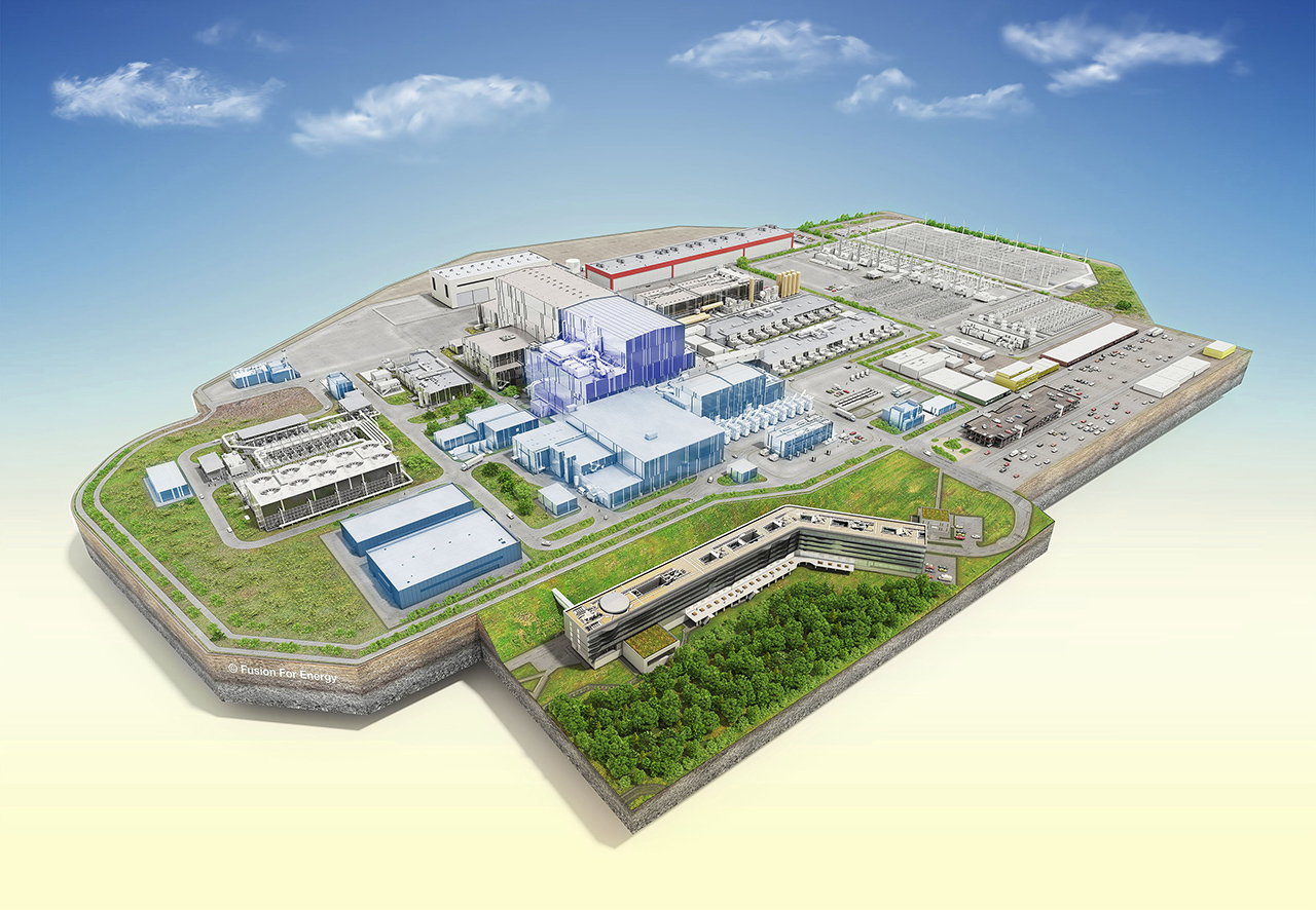
ITER (International Thermonuclear Experimental Reactor) is the world’s largest tokamak, currently under construction in Cadarache, France. Its purpose is not to generate electricity for the grid, but to demonstrate sustained fusion plasmas, validate key technologies (notably tritium breeding), and provide the engineering foundation for a future demonstration fusion power plant (DEMO). ITER is a multinational collaboration involving China, the European Union, India, Japan, the Republic of Korea, Russia, and the United States. First plasma is currently scheduled for around 2026.
The ITER site covers approximately 180 hectares near Saint-Paul-lez-Durance in southern France. Its central platform measures roughly 1 km by 400 m, making it one of the largest levelled surfaces in the world. The complex comprises facilities for assembly, diagnostics, magnets, cryogenics, auxiliary systems, control, and site infrastructure services.
Main Parameters

Cross-section of large ITER tokamak with coils and interior of vacuum vessel.
Free Downloads › Images
ITER will operate with deuterium-tritium fuel at temperatures of around 150 million kelvin, in plasma pulses lasting between 400 and 600 seconds. It is designed to produce about 500 megawatts of fusion power, roughly ten times greater than the power required for plasma heating and confinement.
The vacuum vessel measures 19.4 metres in diameter and 11.4 metres in height, with a distinctive D-shaped cross-section. Its internal volume is approximately 1,400 cubic metres, accommodating around 840 cubic metres of plasma.
The magnetic system consists of 18 superconducting toroidal field coils, each about 17 metres high, 9 metres wide, and weighing 360 tonnes, producing magnetic fields of up to 11.8 tesla in the torus. The central solenoid, standing 13 metres high and 4 metres in diameter, with a mass of about 1,000 tonnes, generates magnetic fields up to 13 tesla to drive the plasma current. The total magnetic energy stored in the system will reach around 41 gigajoules.
Magnets, Vacuum Vessel & Blanket
")
Toroidal field coils of ITER shown with their massive support structures, illustrating the scale and engineering required to generate the strong magnetic fields that confine the plasma.
The magnetic system of ITER comprises powerful superconducting coils made primarily from niobium-tin (Nb₃Sn) and niobium-titanium (NbTi) conductors. These are cooled to around 4 kelvin using supercritical helium to maintain superconductivity. The system includes toroidal field coils, poloidal field coils, and a central solenoid, all integrated to create the helical magnetic configuration required for plasma confinement and stability. The coils must withstand immense electromagnetic forces, with each toroidal field coil subject to loads of tens of meganewtons, and their structural casings are precision-engineered to minimise deformation under these extreme stresses.
The vacuum vessel provides the primary confinement boundary for the plasma and supports the in-vessel components. It is a double-walled stainless-steel structure equipped with internal cooling channels and neutron shielding between the shells. The vessel must endure substantial mechanical, thermal, and electromagnetic loads during plasma operation and disruption events. It also contains numerous ports for diagnostics, heating systems, and remote-handling access. Manufactured in nine toroidal sectors, the completed vessel will be assembled on-site with millimetre-level precision to ensure geometrical accuracy and tight sealing under ultra-high-vacuum conditions.
")
A section of the ITER vacuum vessel during assembly, showing its massive stainless-steel structure and the scale of engineering involved in constructing the tokamak.
Mounted on the inner wall of the vessel, the blanket — which includes the first wall — has a dual function. It absorbs high-energy neutrons, converting their kinetic energy into heat for future energy recovery, and breeds tritium through neutron reactions with lithium contained within the blanket modules. Each module incorporates cooling circuits and structural reinforcement to manage the intense heat and neutron fluxes produced during fusion. The blanket also serves as a radiation shield, protecting the superconducting coils and surrounding structures from neutron damage, and represents one of ITER’s most critical engineering systems for demonstrating reactor-relevant energy capture and fuel sustainability.
Divertor
")
An ITER divertor cassette body, shown during fabrication, which forms the structural backbone for the tungsten plasma-facing components in the divertor.
Impurities and helium “ash” are undesirable products of fusion reactions and must be continuously removed from the plasma to prevent energy losses through radiation. For this purpose, ITER employs a divertor located at the bottom of the tokamak vessel.
The divertor consists of 54 cassette assemblies arranged toroidally around the vacuum vessel. Each cassette has a structural backbone made of austenitic stainless steel and copper alloy, supporting tungsten plasma-facing components, including the dome, inner vertical target, and outer target. Certain regions of the divertor will be exposed to very high heat fluxes, reaching up to 20 megawatts per square metre. The tungsten surface temperature on the inner vertical target is expected to reach about 1,000 °C under normal operating conditions, and up to 2,000 °C under off-normal events.
The divertor is actively cooled by pressurised water circulating through channels beneath the tungsten armour. The cassettes are designed for remote handling and must be positioned with sub-millimetre accuracy, as even small misalignments could compromise performance or cause mechanical damage to the plasma-facing components.
Cooling & Thermal Management
")
Installation of a large heat-rejection system funnel at the ITER site, part of the infrastructure that will remove and dissipate heat from tokamak operation.
The operation of ITER requires the removal of extremely large heat loads. During plasma pulses, the nominal thermal power to be extracted will reach around 500 megawatts, while under peak conditions this may temporarily rise to as much as one gigawatt. To manage these loads, ITER employs several independent water-cooling systems and an extensive cryogenic plant integrated with the tokamak complex.
The tokamak cooling water system provides heat removal for the blanket, divertor, auxiliary systems, and the coil power supply and distribution network. It forms a vast network of piping, extending over tens of kilometres and comprising lines of various diameters. In total, about 25,000 cubic metres of cooling water circulate through the system.
")
Model of the ITER cryostat, the vacuum-insulated structure that encloses the tokamak and maintains the cold environment for its superconducting magnets.
A dedicated cryogenic system maintains the extremely low temperatures required for the superconducting magnets, vacuum pumping units, and selected diagnostic systems. Superconductivity in the magnet coils is sustained using supercritical helium at temperatures near 4 kelvin, while liquid nitrogen at 80 kelvin serves as a pre-cooling medium. The excess heat from all cooling loops is ultimately rejected through induced-draught cooling towers, and a controlled fraction of water is continuously discharged to prevent mineral accumulation, under strict environmental monitoring before release into the Durance River.
Diagnostic Systems
 positioned between the divertor plates. (Credit © ITER Organization, www.iter.org)")
A cutaway of an ITER divertor cassette showing the integrated diagnostic systems — Langmuir probes (in green) positioned between the divertor plates.
The main objective of ITER diagnostics is to obtain the most comprehensive possible information about the plasma and its behaviour. To determine parameters such as temperature, density, shape, position, radiation losses, and fusion power output, ITER is equipped with more than 50 diagnostic systems. These systems will provide the only source of information from inside the vacuum vessel, which, once completed, will be inaccessible to humans and has no optical windows for direct observation.
An in-vessel viewing system will visually inspect the blanket modules after each plasma discharge, while temperature monitoring of the blanket and divertor components will ensure that no part overheats or suffers loss of integrity. Pressure sensors will verify the leak-tightness of the vacuum system, and other diagnostic subsystems will monitor neutron fluxes, plasma radiation, and various key operational parameters. These instruments must provide high-speed, high-precision measurements, and maintain full functionality and calibration throughout the long plasma pulses of 400 to 600 seconds, which are unprecedented in fusion experiments.
External Heating
 connected to the ITER vacuum vessel (left). (Credit © ITER Organization, www.iter.org)")
Cutaway showing the neutral beam injection system (right) connected to the ITER vacuum vessel (left).
In ITER, external heating systems are essential once the plasma temperature exceeds the range in which ohmic heating remains effective. Three main systems are used in combination: Neutral Beam Injection (NBI), Ion Cyclotron Resonance Heating (ICRH) and Electron Cyclotron Resonance Heating (ECRH).
NBI injects high-energy neutral particles that transfer energy to the plasma through collisions, while ICRH employs radio-frequency waves tuned to the natural motion of ions, and ECRH uses millimetre-wave radiation to heat electrons directly. Together, these complementary methods raise the plasma to fusion-relevant temperatures, contribute to current drive and stability control, and enable sustained, long-pulse operation — key steps towards achieving a self-heating, burning plasma in ITER.
Educational materials on ITER are available in the Learning section. You can explore video presentations and animated lectures that explain this major scientific project in fusion research. Finally, you can test your knowledge through an interactive quiz.
ITER — a Major Step Towards Thermonuclear Fusion Learning


History of Nuclear Fusion
")
Lyman Spitzer with “Model A” figure-eight shaped stellarator.
The concept of nuclear fusion originated in the early twentieth century, when scientists realised that the merging of light nuclei into heavier ones could release vast amounts of energy. In 1920, Francis William Aston demonstrated that four hydrogen nuclei have a slightly greater combined mass than a single helium nucleus, implying that mass could be converted into energy according to Einstein’s relation. The first artificial fusion reactions were achieved in 1932 using particle accelerators, when deuterons were fired into targets to produce helium nuclei. These pioneering results confirmed the physical feasibility of fusion, even though sustaining such reactions remained well beyond the capabilities of that time.
In the early 1950s, Lyman Spitzer proposed the stellarator concept (Model A, 1953) — the first toroidal magnetic confinement device designed to hold plasma in equilibrium by external magnetic fields alone. Just a few years later, in 1958, the first tokamak, designated T-1, began operation in the Soviet Union, marking the beginning of a new era in fusion research. Throughout the 1950s and 1960s, the field evolved from fundamental plasma studies to increasingly sophisticated confinement experiments. Devices such as theta pinches and early toroidal machines achieved brief fusion events, while the understanding of plasma instabilities, turbulence and particle losses advanced rapidly. These decades established the two principal magnetic confinement approaches that continue to define fusion research today — tokamaks and stellarators.
")
Scylla, one of the earliest theta-pinch fusion devices, was among the first laboratory machines to achieve controlled thermonuclear fusion reactions.
From the 1970s onwards, fusion experiments became larger, more powerful and increasingly international. Improved magnetic configurations, external heating systems and advanced diagnostics allowed researchers to reach higher temperatures, longer pulses and greater plasma stability. Experimental facilities such as JET, JT-60 and other major tokamaks provided critical insights into plasma behaviour at reactor-relevant conditions. This steady progress ultimately led to the launch of the International Thermonuclear Experimental Reactor (ITER) — the largest collaborative scientific project in history — designed to demonstrate net energy gain from controlled thermonuclear fusion and to serve as the engineering bridge toward a future demonstration power plant (DEMO).
In parallel with magnetic confinement research, inertial confinement fusion (ICF) developed as a complementary approach, using high-power lasers to compress and ignite small fuel pellets. After decades of gradual improvement, a historic milestone was achieved in December 2022, when the National Ignition Facility (NIF) reported fusion ignition — producing more fusion energy within the target than the laser energy delivered to it. This achievement symbolises the culmination of decades of incremental progress across multiple fusion pathways, bringing the goal of practical and sustainable fusion energy closer to realisation.

Thermonuclear Fusion Power Plant
")
A simple schematic of a fusion power plant, showing a tokamak producing heat from fusion reactions that is transferred to a conventional steam cycle to generate electricity.
A thermonuclear fusion power plant aims to harness the same physical process that powers the Sun — the fusion of light nuclei into heavier ones — to generate clean and safe energy. Fusion offers major environmental advantages: it emits no greenhouse gases during operation and uses fuels that are abundant and globally accessible. The most feasible reaction is that of deuterium and tritium, where deuterium can be extracted from water and tritium is bred from lithium within the reactor’s blanket structure. Achieving the conditions necessary for ignition — temperatures above 100 million kelvin and sufficient plasma confinement — requires large magnetic devices such as tokamaks or stellarators.
The energy released in the fusion process appears mainly as high-energy neutrons, which transfer their kinetic energy to the surrounding blanket. This blanket converts the neutron energy into heat that drives a conventional steam turbine cycle, while simultaneously breeding tritium to sustain the fuel cycle. Materials used in this region must withstand intense neutron bombardment, thermal stress, and erosion, while maintaining structural integrity and low levels of induced radioactivity.
")
Toroidal coils of ASDEX Upgrade fusion device can be seen during its construction.
Fusion reactors are designed with inherent safety features. The quantity of fuel present in the plasma at any given moment is extremely small, no chain reaction is possible, and any disturbance causes the plasma to extinguish almost instantly. In contrast to fission, fusion does not generate long-lived fission products or plutonium. However, the structural components inside the vacuum vessel become neutron-activated, particularly the first wall, divertor, and blanket modules. For this reason, after extended operation the interior will be inaccessible to personnel and will require remote maintenance.
The radioactive by-products of fusion are limited to these activation materials, whose radioactivity decreases significantly over time as short-lived isotopes decay. After an appropriate cool-down period — typically several decades — most components can be handled safely, recycled, or reused. This contrasts sharply with the thousands of years required for the decay of long-lived fission waste, providing fusion with a major environmental advantage.
")
An illustration hinting that high-power lasers and inertial confinement fusion represent another potential pathway toward a future fusion power plant.
While significant challenges remain — such as continuous operation, tritium breeding efficiency, materials development, and overall plant economics — projects such as ITER and its successor DEMO are intended to demonstrate the technological viability of fusion power. When realised, a thermonuclear fusion power plant will resemble a conventional generating station from the outside, but at its core it will produce heat not by splitting atoms, but by fusing them — offering a virtually limitless, safe, and sustainable energy source for future generations.
Educational materials on the fusion power plant are available in the Learning section. You can explore video presentations and animated lectures explaining the main principles and the key challenges on the path towards the future of electricity generation. Finally, you can test your knowledge through an interactive quiz.
Fusion Power Plant as a Clean Energy Source Learning